D2 Drive User Guide v1.8 4. Wiring
HIWIN Mikrosystem Corp. 51
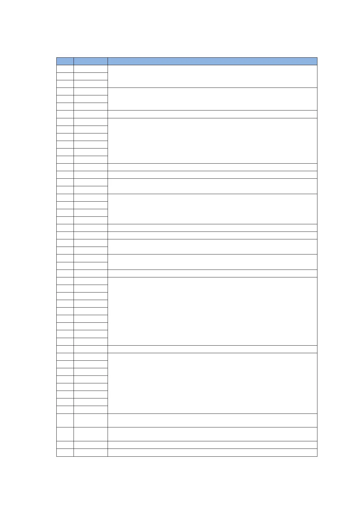
CN6 pin assignment:
Table 4-8
Low-speed (500 Kpps) pulse command
Channel 1: Pulse, CW, A-phase
Low-speed (500 Kpps) pulse command
Channel 2: Dir, CCW, B-phase
Ground reference for digital signal
Feedback pulse output (buffered encoder or emulated encoder)
RS422
Z-phase output (open collector)
Analog command input for the velocity/torque (+/- 10 V)
Analog voltage output (+/- 10V) for monitoring motor torque (only for D2T model)
Analog voltage output (+/- 10V) for monitoring motor speed (only for D2T model)
High-speed (4 Mpps) pulse command
Channel 1: Pulse, CW, A-phase
High-speed (4 Mpps) pulse command
Channel 2: DIR, CCW, B-phase
Common point for general-purpose input signal (Sink or Source)
General-purpose input signal (programmable function)
D2 model: N/A; D2T model: I10.
General-purpose output signal (programmable function)
D2 model: N/A; D2T model with the frame A, B, or C: O5+;
D2T model with the frame D: brake output/O5+.
D2 model: N/A; D2T model with the frame A, B, or C: O5-;
D2T model with the frame D: brake output/O5-.