OM-285922 Page 18
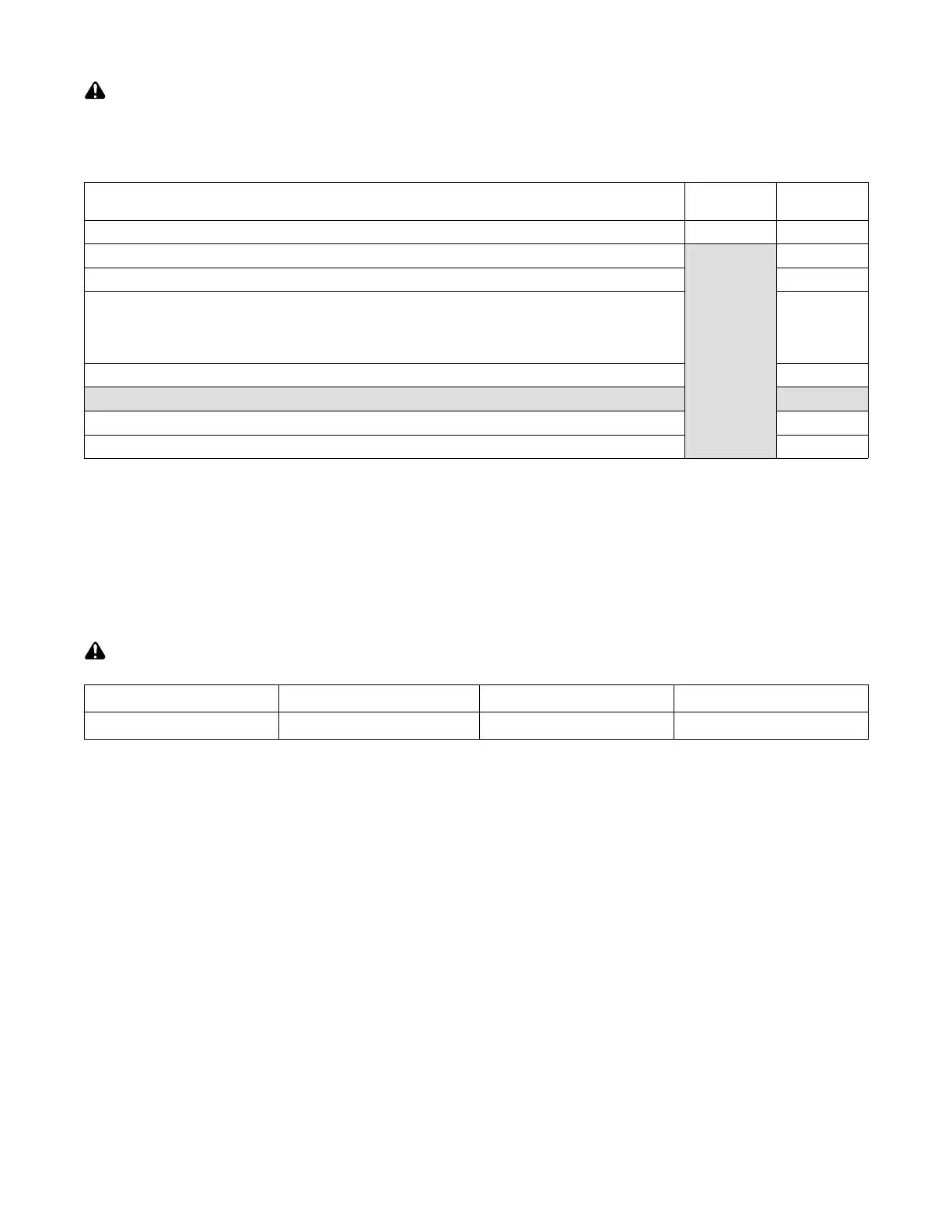
5-3. Electrical Service Guide
Elec Serv 2020-02
Failure to follow these electrical service guide recommendations could create an electric shock or fire hazard. These recommenda-
tions are for an individual branch circuit sized for the rated output and duty cycle of one welding power source.
In individual branch circuit installations, the National Electrical Code (NEC) allows the receptacle or conductor rating to be less than
the rating of the circuit protection device. All components of the circuit must be physically compatible. See NEC articles 210.21, 630.11,
and 630.12.
50/60 Hz
1-Phase
50/60 Hz
1-Phase
Rated Supply Voltage (V) 120 240
Rated Maximum Supply Current I
1max
(A)
A 15 or 20
ampere
individual
branch circuit
protected by
time-delay
fuses or circuit
breaker is
required. See
Section 5-5.
32
Maximum Effective Supply Current I
1eff
(A) 15
Maximum Recommended Standard Fuse Rating In Amperes
Time-Delay Fuses
40
Normal Operating Fuses
45
Maximum Recommended Supply Conductor Length In Feet (Meters)
34 (10)
Raceway Installation
Minimum Supply Conductor Size In AWG (mm
)
12
Minimum Grounding Conductor Size In AWG (mm
12
Reference: 2020 National Electrical Code (NEC) (including article 630)
1 If a circuit breaker is used in place of a fuse, choose a circuit breaker with time-current curves comparable to the recommended fuse.
2 “Time-Delay” fuses are UL class “RK5” . See UL 248.
3 “Normal Operating” (general purpose - no intentional delay) fuses are UL class “K5” (up to and including 60 amps), and UL class “H” ( 65 amps and
above).
4 Maximum total length of copper input conductors in entire installation, raceway and/or flexible cord.
5 Raceway conductor data in this section specifies conductor size (excluding flexible cord or cable) between the panelboard and the equipment per
NEC Table 310.15(B)(16) and is based on allowable ampacities of insulated copper conductors having a temperature rating of 75°C (167°F) with not
more than three single current−carrying conductors in a raceway.
5-4. Input Power Extension Cord Data
Use extension cord only for temporary wiring. Remove extension cord immediately after completing the project.
Input 17 2018-11
Cord Type Minimum Conductor Size Number of Conductors Maximum Cord Length
Heavy Duty (Hard Usage) 12 AWG (4 mm
) 3 50 ft (15 m)
. Read OSHA Standard 1910.334 for more information on the use of cord and plug connected equipment.
Read National Electrical Code (NEC) Article 590 for more information on temporary wiring.