WORKING WITH THE COMPACT CRANE
U.C10.00.00.EN Version 2.0 57
6.7.8 Explanation of display during lifting
While working with the crane, if the crane is set to crane operation, the following information is shown on the
remote control display. The values that appear on the display are explained below.
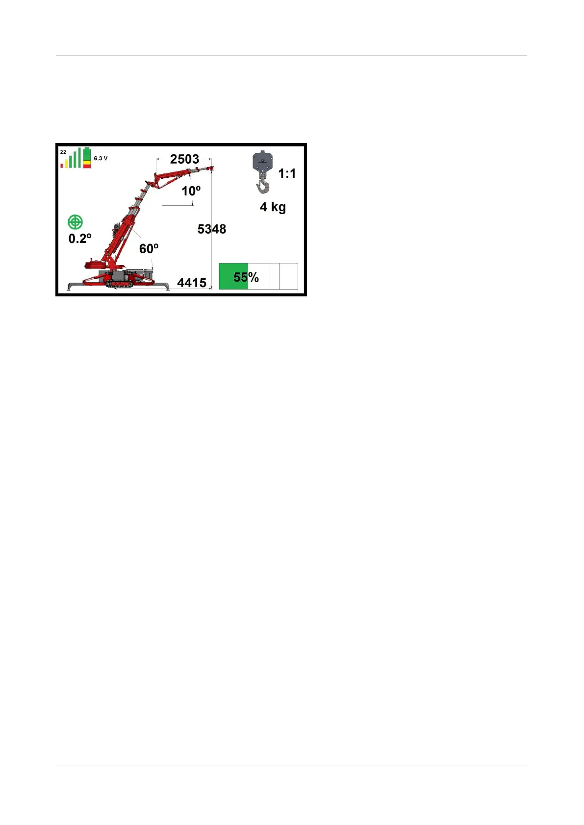
Figure: 76
The transmission frequency is shown at the top left. See figure 76; here it is set to 22.
The signal strength is indicated by 5 vertical bars. If the strength is good, they are all shown, as in figure 76.
As the signal weakens, the green bars disappear first, then the yellow and red ones.
The battery state of charge is shown in the battery symbol in the top-left corner of the screen. When the
battery is fully charged, 3 green blocks, 1 yellow and 1 red are shown, as in figure 76. As the battery
discharges, the blocks go out, one at a time.
The voltage is shown in volts. In figure 76 this is 6.3 V.
The degree of levelling of the machine is also shown. This is indicated by the green circles in the middle. In
figure 76 the crane is 0.2° out of level. Which side it is leaning towards is not shown. This can be seen on the
level (see figure 32).
The position of the main mast is 60° in figure 76.
The position of the jib is 10° in figure 76.
The radius of the outreach is 4415 mm in figure 76.
The lifting height is 5348 mm in (figure 76).
The length of the jib is 2503 mm in figure 76.
The reeving is 1:1, so one cable is being used for lifting.
There is 4 kg in the lifting hook.
The crane is loaded at 55% in figure 76.
As can be seen in figure 76, the ballast is extended. When the ballast is retracted it moves on the display, and
when the ballast is removed from the crane it is no longer shown on the display.