WORKING WITH THE COMPACT CRANE
U.C10.00.00.EN Version 2.0 41
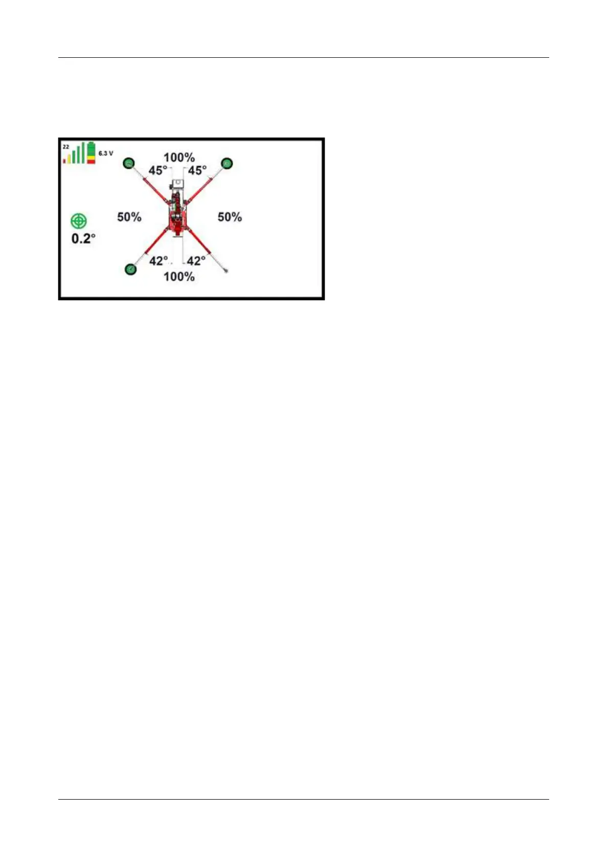
6.5.3 Interpreting the display while setting the outriggers
While the outriggers are being set, info about how much may be lifted and how the crane is positioned is shown
on the display of the remote control. This is explained below.
Figure: 37
The transmission frequency is shown at the top left. See figure 37; here it is set to 22.
The signal strength is indicated by 5 vertical bars. If the strength is good, they are all shown, as in figure 37.
As the signal weakens, the green bars disappear first, then the yellow and red ones. If the signal is too
weak, you can select a different frequency by switching off the transmitter and machine and switching
them on again. See section 6.2.1.
The battery state of charge is shown in the battery symbol in the top-left corner of the screen. When the
battery is fully charged, 3 green blocks, 1 yellow and 1 red are shown, as in figure 37. As the battery
discharges, the blocks go out, one at a time.
The voltage is shown in volts. In figure 37 this is 6.3 V.
The degree of levelling of the machine is also shown. This is indicated by the green circles in the middle. In
figure 37 the crane is 0.2° out of level. Which side it is leaning towards is not shown. This can be seen on
the level (see figure 32).
The left-front outrigger leg is set at 45° in figure 37.
The right-front outrigger leg is set at 45° in figure 37.
The left-rear outrigger leg is set at 42° in figure 37.
The right-rear outrigger leg is set at 42° in figure 37.
At the front of the crane 100% of the lifting capacity may be lifted in figure 37.
On the right side of the crane 50% of the lifting capacity may be lifted in figure 37.
At the rear of the crane 100% of the lifting capacity may be lifted in figure 37.
On the left side of the crane 50% of the lifting capacity may be lifted in figure 37.
A green circle is shown by three of the four outrigger legs in figure 37. The outrigger leg without a circle is
not set properly; this outrigger leg is probably not in contact with the ground. When a green circle appears,
it is set properly.