ThinPrep
®
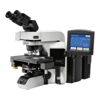
Integrated Imager Operator’s Manual
2.3
INSTALLATION
The microscope and controller are mechanically and electronically connected and should
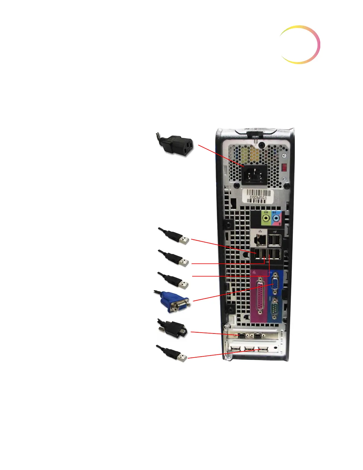
NOT be separated. The cabling between the controller and the computer may be disconnected
and reconnected, see
Figure 2-2.
Before disconnecting any of the components, be sure to observe how they are originally connected.
See
Figure 2-2.
Figure 2-2 Integrated Imager Interconnections
Note:
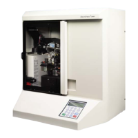
The computer may be set up to face either side, or with the use of the extension cable set, it
can be placed further away from the microscope and controller. Your final configuration may
look slightly different than
Figure 2-2. The cable connections to the computer ports remain the
same.
Computer AC power cord
1 (USB cable)
2 (USB cable)
3 (USB cable)
VGA (for touch screen)
Firewire (for internal camera)
4 (USB cable)