INSTALLATION
2.6
ThinPrep
®
Integrated Imager Operator’s Manual
CAUTION:
Do not use filters on the collector or in the objectives.
Filters
- To ensure that the imaging camera images the cell spot at the correct gray scale for which
the imaging is intended, do
not place filters
in the illumination path on the collector or in the
objectives.Adjusting the X,Y Axis Stage Control Knob Tension and Height
The X- and Y-axis stage control knob tension and height may be adjusted to suit the operator’s
preference. See
Figure 2-5.
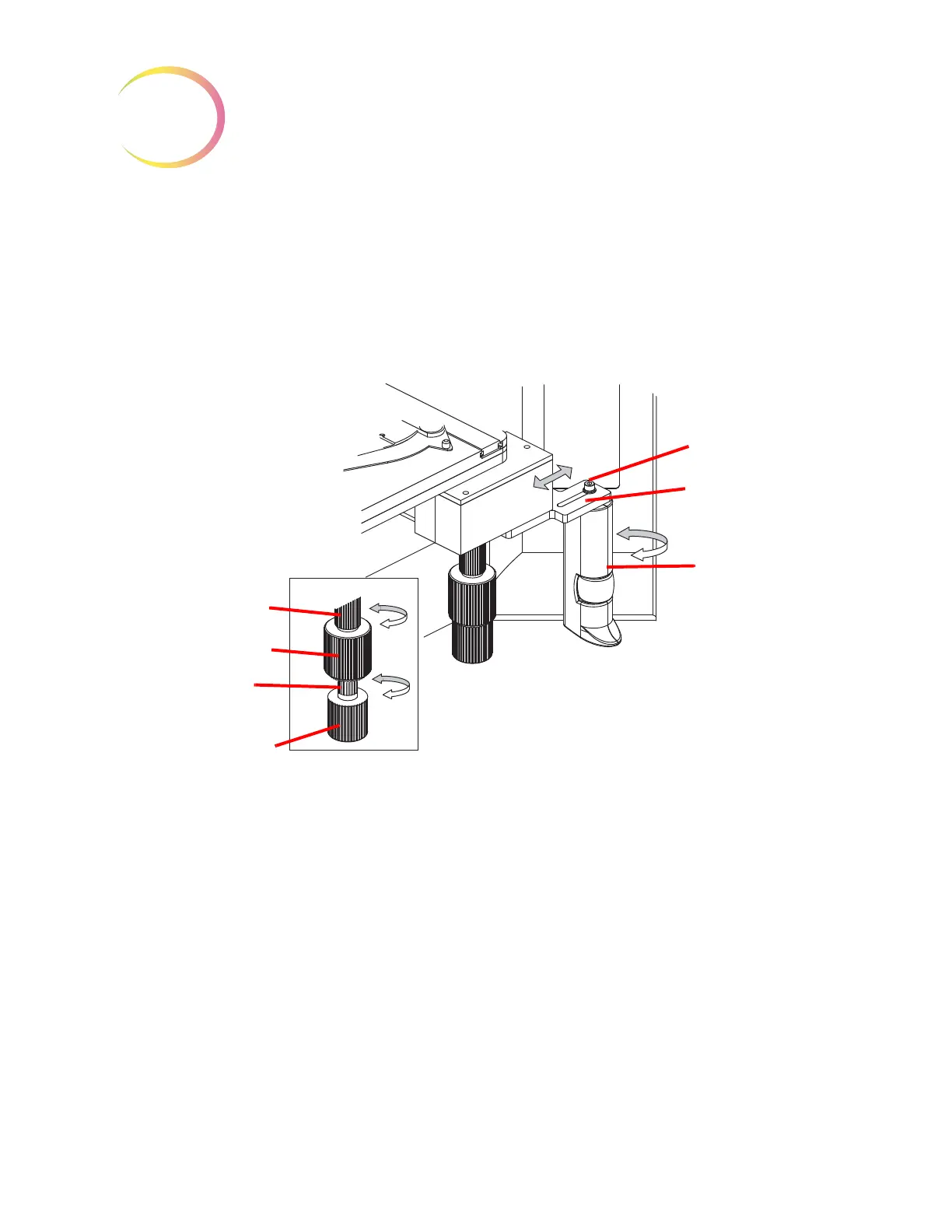
Figure 2-5 Adjust Substage Controls
The Y-axis is adjusted by accessing the adjustment sleeve above the knob. To adjust the X-axis, pull
the X- and Y-axis stage control knobs apart to reveal the adjustment sleeve of the X-axis stage
control. To loosen the tension, turn the adjustment sleeves counterclockwise. For a tighter tension,
turn the sleeve clockwise for either control.
To adjust the height, the X- and Y-axis stage control knobs may be slid downward or upward on
the vertical axis of the assembly shaft.
Leave a small gap between the X- and Y-axis stage control knobs, to ensure there is no interference
in the movement of either knob.
Adjust the Review Control Position
The Review Control may be positioned closer or further from the stage controls via an adjustment
slot. See
Figure 2-5.
Using the Allen screwdriver that comes with the Integrated Imager (see Figure 1-4), loosen but do
not remove the Allen screw that holds the review control to the mounting bracket.
Y-Axis tension adjust-
ment sleeve
Y-Axis stage control
X-Axis tension
adjustment sleeve
X-Axis stage control
Allen screw
Adjustment slot
Rotate review
control