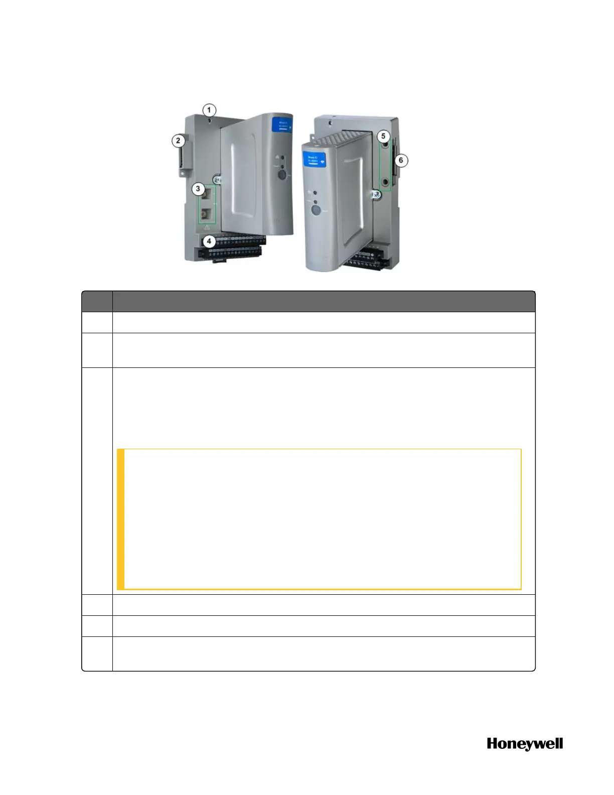
Figure 3-12: Expansion I/O
Item Description
1 Chassis ground
2 Left expansion connector: used for connecting with controller, expansion I/O
module or left end plate.
3 Rotary switch (two): used for setting the address of IOM. The controller can
configure and communicate with IOM according to this address. Set the
switches to the two digit address ranging from 01 to 98. The upper switch (10) is
used to set the tens digit and the lower switch (1) sets the ones digit. See
"Mounting the Controller with Expansion IOM" on page1 for more information.
ATTENTION:
l The address must be unique across all I/O modules connected to
the same ControlEdge 2020 controller.
l Unless the location is known to be non-hazardous, do not adjust the
switches while the equipment is powered.
l Do not set the switch index bigger than 98, or else the system LED
of IOM status indicator would blink with yellow, reflecting that IOM is
unable to establish the communication with the Controller.
4 Terminal strips: used for connecting I/O cable from the field.
5 Screw holes: used for locking IOTAs between two expansion I/O Modules.
6 Right expansion connector: used for connecting with expansion I/O module or
right end plate.
34
Chapter 3 - Hardware
 Loading...