49
output can be configured via ControlEdge Builder.
8. Select the corresponding channel, and configure parameters.
Configuring serial modules
The section introduces how to add and configure a serial
communication module. Up to six serial modules can be added.
1. From the Home Page, under I/O and Communications, click
Configure Modules > Configure Serial Modules.
2. Click Add Serial Module, the Add Serial Module dialog appears.
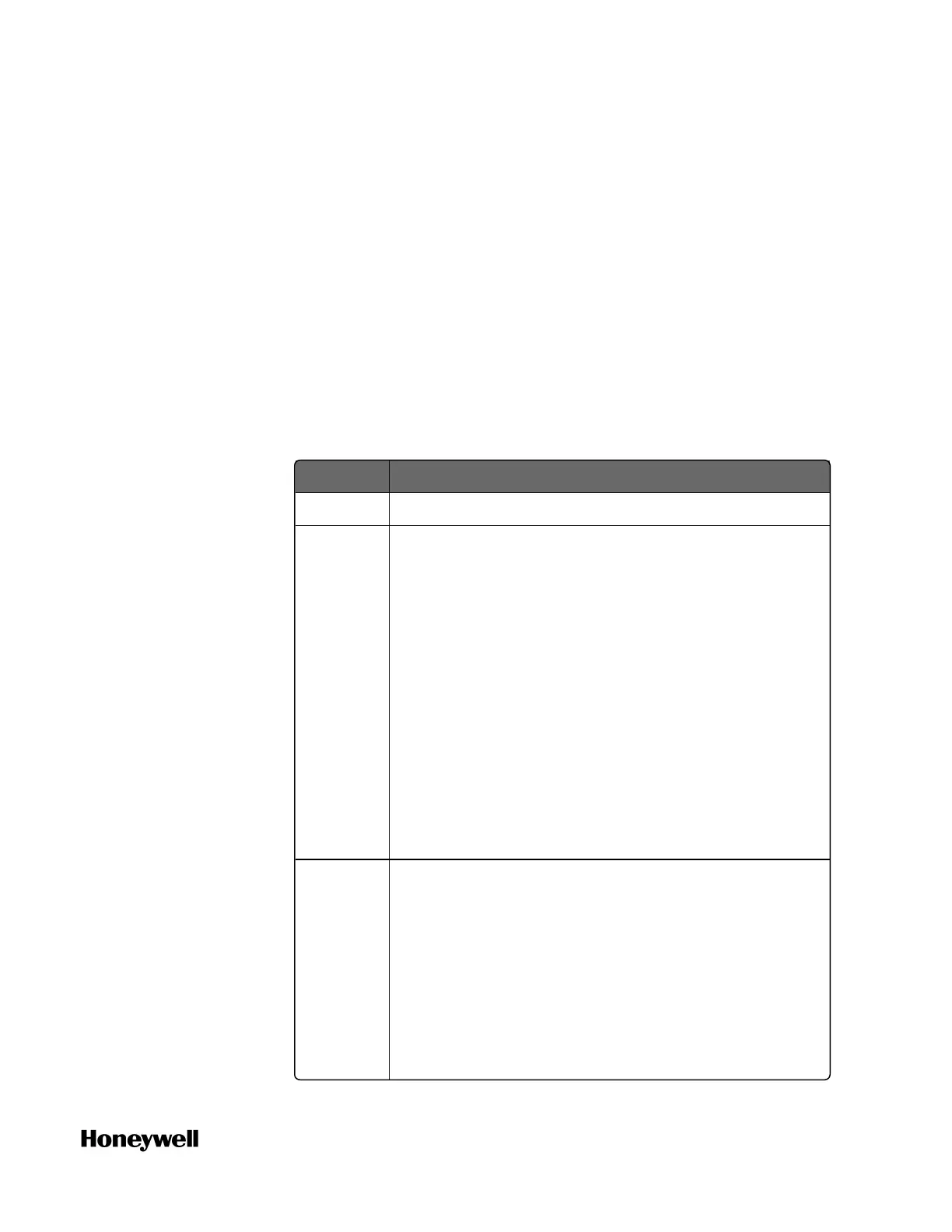
3. Select the Type, assign the Rack and Slot for the module.
See the following table for the parameter descriptions:
Parameter Description
Type Serial module type: 900ES1: Serial Comm
Rack Rack address:
l If controller redundancy is enabled, the rack
address range is from 1 to 99.
l If controller redundancy is disabled, the rack
address range is from 0 to 99. 0 is only for the
local I/O rack.
l For an expansion I/O rack, the address must be
the same with the EPM address configured on
1x and 10x rotary switches.
For details about the rotary switches, see
“Assembling I/O racks” in the ControlEdge 900
Controller Hardware Planning and Installation
Guide.
Slot Slot number: the location of the I/O module mounted
in the rack
l If the I/O module is installed in a 4-slot rack, the
slot number is ranging from 1 to 4.
l If the I/O module is installed in an 8-slot rack,
the slot number is ranging from 1 to 8.
l If the I/O module is installed in a 12-slot rack,
the slot number is ranging from 1 to 12.
Chapter 4 - Software
 Loading...