51
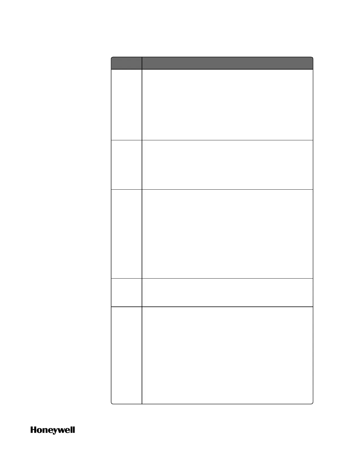
Protocol Description
If you select Modbus RTU Slave:
l Data Bits is set as 8 by default.
l There are two more options to configure: Slave ID
and Mapping.
If the Mapping is empty, you must add a mapping
table first. See "Adding a Modbus Slave mapping
table" on page1 for more information.
Modbus
RTU
Master
The controller acts as the Modbus Master and used for
communication between The controller and third-party
Modbus Slave devices, for example I/O modules.
If you select Modbus RTU Master, Data Bits is set as 8
by default.
Modbus
ASCII
Slave
The controller acts as the Modbus Slave and used for
communication between:
l Controller and SCADA
l Controller and third-party Modbus Master
If you select Modbus ASCII Slave, you must configure
two more options: Slave ID and Mapping. If the Mapping
is empty, you must add a mapping table first. See
"Adding a Modbus Slave mapping table" on page1 for
more information.
Modbus
ASCII
Master
The controller acts as the Modbus Master and used for
communication between The controller and third-party
Modbus Slave devices, for example: I/O modules.
User
Defined
User Defined protocol.
When you select this option, the Delimiter Mode
(Optional) panel appears including three settings: Read-
interval Timeout (ms), Max Length (Bytes) and End
Delimiter (Hex). You can configure them optionally to
validate if a data frame is sent completely.
l Read-interval Timeout (ms): The interval between the
last data packet sent and the first keepalive probe,
ranging from 0 to 10000 (ms). If the interval
between the arrivals of any two bytes exceeds this
Chapter 4 - Software
 Loading...