# Item
Terminal or
connector
Connect to
L IB2 BUS +12V 12VDCsupply terminal
– 0VDC supply terminal
C IB2 busC
D IB2 busD
M Request to
exit (RTE),
optional
RTE To request to exit button
– To request to exit button [–] terminal.
Default supervision: EOLR (2K). For details and more
options, see Wiring Inputs (Zones) on page39. Terminate
using resistors if not used.
N EXIT Reader
(Reader2),
optional
+12V Exit reader power input [+].
– Exit reader power input [–]
D0 Exit reader data0
D1 Exit reader data1
T Exit reader tamper.
– Exit reader tamper [–]
Minimum Connections
The DCM simply needs wiring to the IB2 data bus, and the following minimum
connections:
1. Attach a Wiegand reader to the ENTRY Reader terminals.
2. Attach the door lock to the Door Strike/Lock terminals.
3. Attach a requestto exit button to the RTE terminals.
4. Attach a door contact to the DSM terminals.
5. Optionally, you can connect the reader buzzer and red LED controllines
to the appropriate terminals on the DCM to give extra feedback.
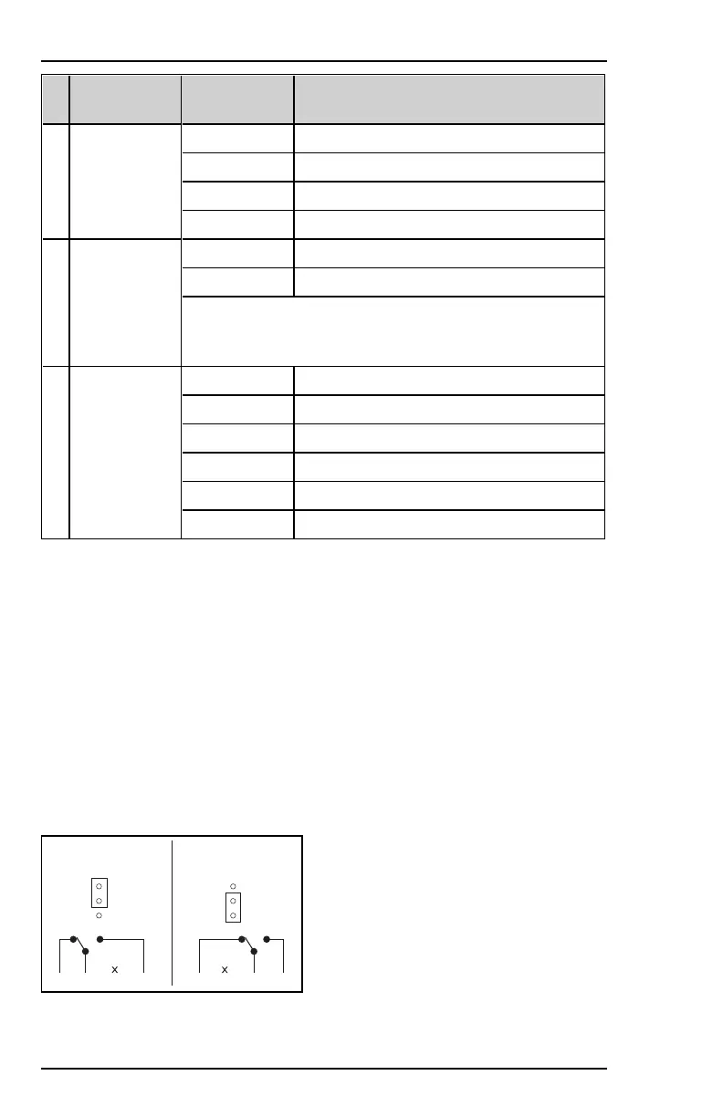
Relay Jumper
NC C NO12V
3
2
1
A
3
2
1
B
NC C NO12V
A: jumper in position 2–3(default). Normal relay operation.
74 800-23044 Rev. A draft_11
Installation and Setup Guide Honeywell MAXPRO Intrusion MPIP2000U/3000U Series
 Loading...