16 Notifier SLC Wiring Manual — P/N 51253:U5 12/20/2017
Section 2: Wiring Requirements
2.1 Recommended SLC Wiring
Depending on the panel, there are two recommended options for SLC wiring:
• Twisted, unshielded pair: NFS-320, NFS2-640, NFS-640, NFS2-3030, NFS-3030, LCM-320, LEM-320, LIB-200A, LIB-400.
Maximum resistance 50 ohms per branch. See Table 2.1.
Maximum capacitance: 0.5 µFarads per branch.
• Twisted-shielded pair: AFP-100, AFP-200, AFP-300/400, LIB-200, AIM-200.
Maximum resistance 40 ohms per branch. See Table 2.2.
To maximize distance on the SLC loop, use the recommended type of wire. Using other wiring types makes the SLC circuit more sus-
ceptible to electrical interference and thus reduces its maximum loop length.
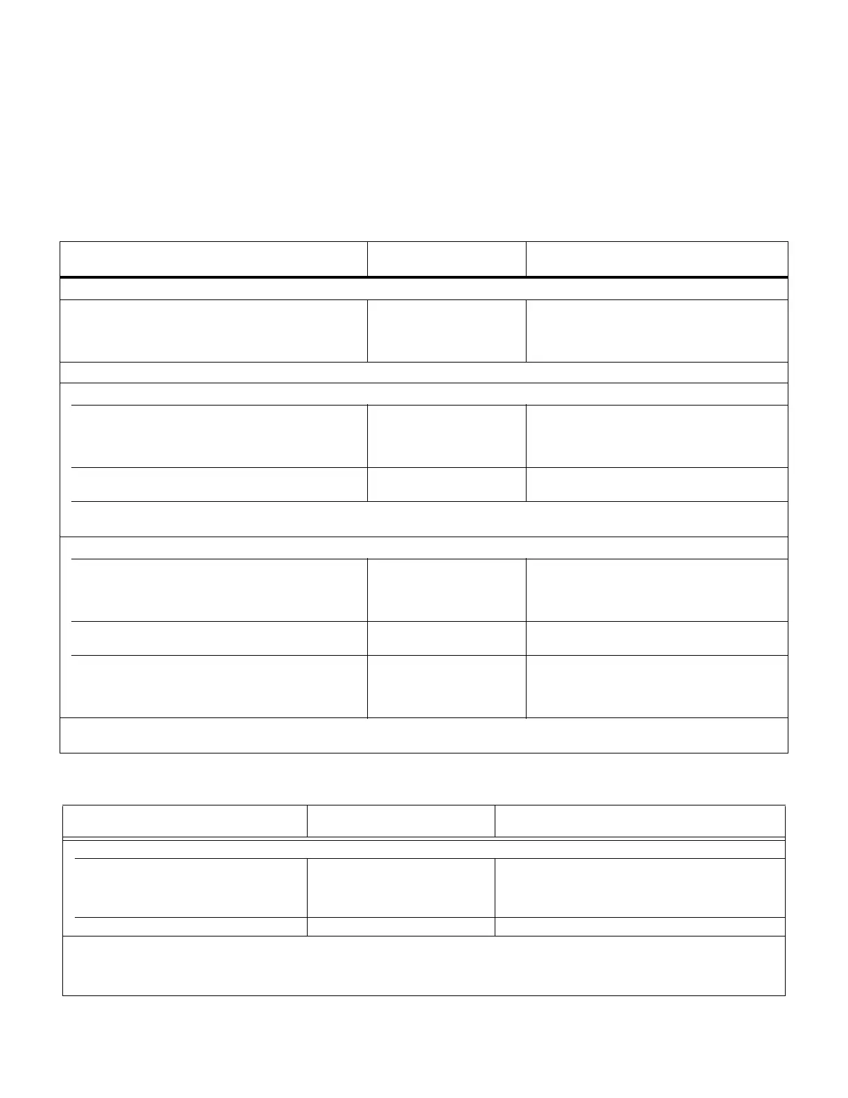
FACP:
Wire Type and Limitations
Recommended
Max. Distance
Wire Gauge
LIB-200A or LIB-400 on AM2020/AFP1010 (See Table 2.2 for LIB-200.)
RECOMMENDED: Twisted unshielded pair, 12 to 18 AWG
(3.31 mm² to 0.82 mm²†). 50 ohms max per length of Style
6 and 7 loops. 50 ohms per branch max for Style 4 loops
12,500 ft. (3,810 m)
9,500 ft. (2,895.6 m)
6,000 ft. (1,828.8 m)
3,700 ft. (1,127.76 m)
12 AWG/3.31 mm²
14 AWG/2.08 mm²
16 AWG/1.31 mm²
18 AWG/0.82 mm²
NOTE: Twisted-shielded pair or untwisted unshielded wire is not recommended for use with LIB-200A or LIB-400.
NFS-640 and LEM-320 on NFS-640
RECOMMENDED: Twisted-unshielded pair, 12 to 18 AWG
(3.31 mm² to 0.82 mm²). 50 ohms maximum per length of
Style 6 & 7 loops. 50 ohms per branch maximum for Style 4
loop.
12,500 ft. (3,810 m)
9,500 ft. (2,895.6 m)
6,000 ft. (1,828.8 m)
3,700 ft. (1,127.76 m)
12 AWG (3.31 mm²)
14 AWG (2.08 mm²)
16 AWG (1.31 mm²)
18 AWG (0.82 mm²)
Untwisted, unshielded wire, in conduit or outside of
conduit.
1,000 ft. (304.8 m) 12 to 18 AWG (3.31 mm² to 0.82 mm²)
Note: Twisted-shielded pair is not recommended for use with this panel.
Note: Maximum total capacitance of all SLC wiring (both between conductors and from any conductor to ground) should not exceed 0.5 microfarads.
NFS-320, NFS-320SYS, NFS2-640, LEM-320 on NFS2-640, LCM-320/LEM-320 on NFS-3030/NFS2-3030
RECOMMENDED: Twisted-unshielded pair, 12 to 18
AWG (3.31 mm² to 0.82 mm²). 50 ohms, maximum per
length of Style 6 & 7 loops. 50 ohms per branch maximum
for Style 4 loop.
12,500 ft. (3,810 m)
9,500 ft. (2,895.6 m)
6,000 ft. (1,828.8 m)
3,700 ft. (1,127.76 m)
12 AWG (3.31 mm²)
14 AWG (2.08 mm²)
16 AWG (1.31 mm²)
18 AWG (0.82 mm²)
Untwisted, unshielded wire, in conduit or outside of
conduit.
5,000 ft. (1,524 m)
3,700 ft. (1,127.76m)
12 to 16 AWG (3.31 mm² to 1.31 mm²)
18 AWG (0.82 mm²)
Twisted, shielded pair
Note:
• Shields must be isolated from ground.
• Shields should be broken at each device.
5,000 ft. (1,524 m)
3,700 ft. (1,127.76m)
12 to 16 AWG (3.31 mm² to 1.31 mm²)
18 AWG (0.82 mm²)
Note: Maximum total capacitance of all SLC wiring (both between conductors and from any conductor to ground) should not exceed 0.5
microfarads.
Table 2.1 Wiring Recommendations: NFS-320, NFS2-640, NFS-640, NFS2-3030, NFS-3030, LCM-320, LEM-320, LIB-200A, and
LIB-400
FACP:
Wire Type and Limitations
Recommended
Max. Distance
Wire Gauge
AFP-100
Twisted, shielded pair, 40 ohms maximum per
length of Style 6 and 7 loops. 40 ohms per
branch maximum for Style 4 loops.
10,000 ft. (3,000 m)
8,000 ft. (2,400 m)
4,875 ft. (1,450 m)
3,225 ft. (980 m)
12 AWG (3.31 mm²)
14 AWG (2.08 mm²)
16 AWG (1.31 mm²)
18 AWG (0.82 mm²)
Untwisted, Unshielded 1,000 ft. (300 m) 12-18 12 to 18 AWG (3.31 mm² to 0.82 mm²)
Note: Twisted-unshielded pair wire is not recommended for use with this panel.
Table 2.2 Wiring: AFP-100, AFP-200, AFP-300/400, LIB-200, AIM-200 (1 of 2)
 Loading...


