26 Notifier SLC Wiring Manual — P/N 51253:U5 12/20/2017
Section 5: SLC Circuits with Isolators
5.1 Overview
There are two isolator devices used to protect critical elements of the FlashScan-mode or CLIP-mode SLC loop from faults on other SLC
branches or segments.
• Fault Isolator Module ISO-X
• Isolator Detector Base B224BI, B224BI-IV
• Six fault isolator module ISO-6
To comply with NFPA Style 7 requirements, one of these devices must be used on both sides of a device: one isolator base and one iso-
lator module, two fault-isolator modules, or two circuits on a six-fault isolator module, for example.
A Fault Isolator Module on both sides of a device, or the combination of an Isolator and Isolator Module are required to comply with
NFPA Style 7 requirements. One isolator of ISO-6 meets the Isolator Module requirements. To comply with NFPA Style 7 requirements,
one of these devices must be used on both sides of a device: two fault isolator modules, one isolator base and one isolator module, for
example.
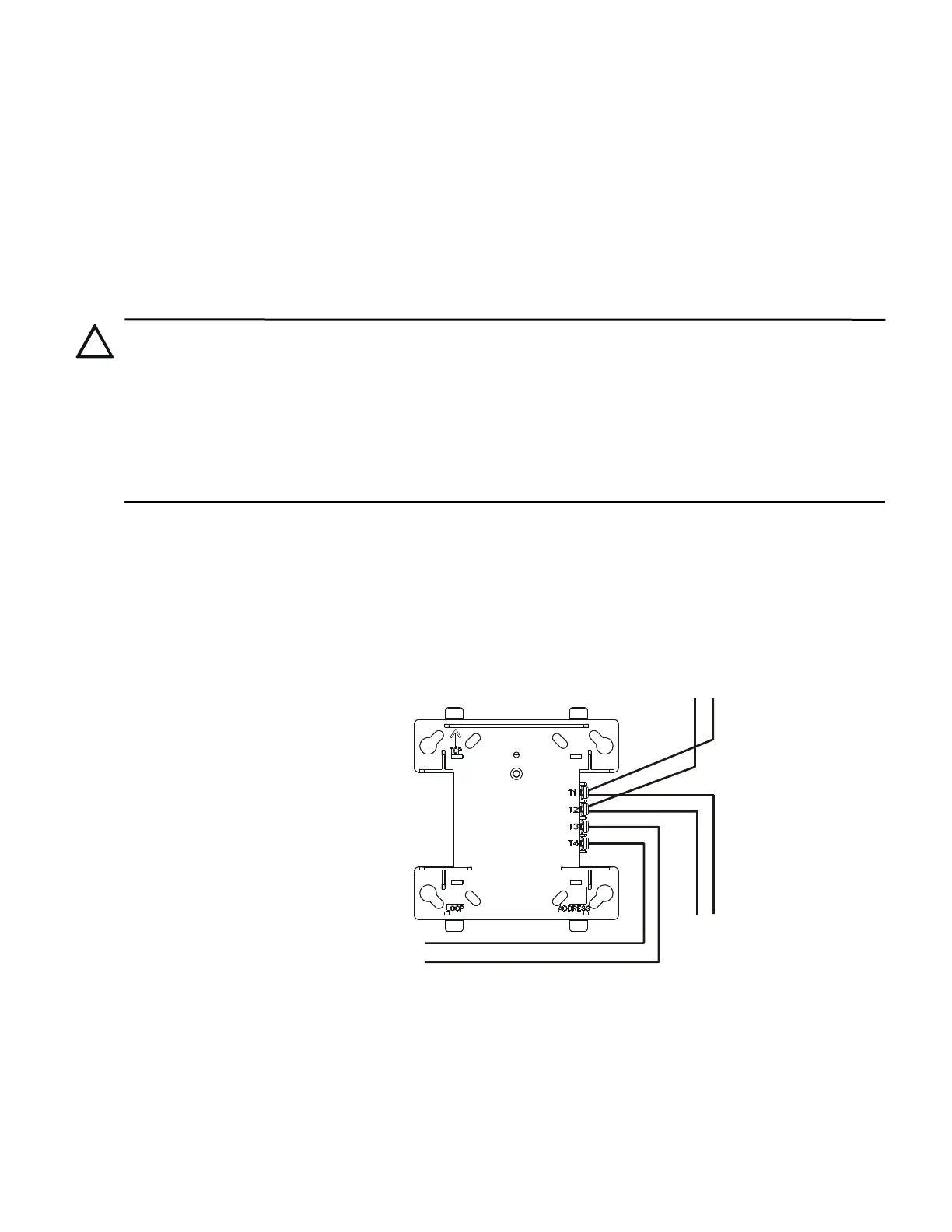
5.2 Fault Isolator Modules
The ISO-X module continuously monitors the circuit connected to terminals 3(–) and 4(+). Upon powerup, an integral relay is latched
on. The module periodically pulses the coil of this relay. A short circuit on the SLC resets the relay. The module detects the short and dis-
connects the faulted SLC branch or segment by opening the positive side of the SLC (terminal 4). This isolates the faulted branch from
the remainder of the loop preventing a communication problem with all other addressable devices on the remaining branches (labeled
“Continuation of the SLC” in the figure below). During a fault condition, the control panel registers a trouble condition for each address-
able device which is isolated on the SLC segment or branch. Once the fault is removed, the module automatically reapplies power to the
SLC branch or segment. Figure 5.1 shows a Style 4 example for wiring of an Isolator Module. ISO-6 has the same functionality; see
Figure 5.2.
CAUTION: ISOLATOR LIMITS
IF RELAY OR SOUNDER BASES ARE NOT USED, A MAXIMUM OF 25 ADDRESSABLE DEVICES CAN BE
CONNECTED BETWEEN ISOLATOR MODULES AND/OR BASES. WHEN RELAY OR SOUNDER BASES ARE USED,
THE MAXIMUM NUMBER OF ADDRESSABLE DEVICES THAT CAN BE CONNECTED BETWEEN ISOLATORS IS
REDUCED TO SEVEN. ISOLATOR MODULES WILL NOT FUNCTION PROPERLY WHEN THESE LIMITS ARE
EXCEEDED.
WHEN MORE THAN 100 ISOLATOR MODULES AND/OR ISOLATOR BASES ARE CONNECTED FROM THE AFP-300
OR AFP-400 TO AN SLC LOOP, THE ADDRESS CAPACITY OF THE LOOP IS REDUCED BY TWO (2) ADDRESSES
FOR EVERY ISOLATOR DEVICE IN EXCESS OF 100. THE ADDRESS CAPACITY OF THE LOOP IS REDUCED BY
TWO (2) ADDRESSES FOR EVERY ISOLATOR DEVICE IN EXCESS OF 200 WHEN THE ISOLATOR MODULES
AND/OR ISOLATOR BASES ARE CONNECTED TO THE SLC LOOP FROM THE NFS-320, NFS-320SYS, NFS2-640,
NFS2-3030, NFS-3030, NFS-640, AFP-100, OR AFP-200.
SLC
Isolated branch
of the SLC
SLC-isowire2.wmf
Continuation
of the SLC
OUT
OUT
IN
IN
Figure 5.1 Wiring the ISO-X Isolator Module
 Loading...


