Notifier SLC Wiring Manual — P/N 51253:U5 12/20/2017 29
NFPA Style 4 SLC Using Isolator Modules SLC Circuits with Isolators
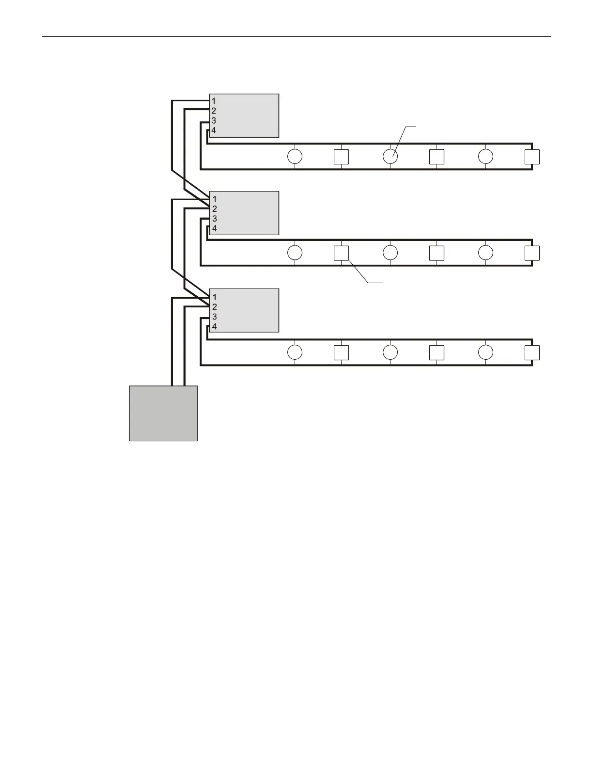
5.4 NFPA Style 4 SLC Using Isolator Modules
A variation of a Style 4 operation using isolator modules to protect each branch of the SLC. Refer to Figure 5.1 on page 26 and
Figure 5.2 on page 27 for isolator module wiring and to Section 5, “SLC Circuits with Isolators” for limitations.
Two-wire Addressable Detector
Addressable Pull Station
SLC-style4iso.wmf
Control Panel
SLC
B– B+
Isolated Branch
Isolator Module
Isolator Module
Isolator Module
Isolated Branch
Isolated Branch
Figure 5.4 NFPA Style 4 SLC Using ISO-X Modules
 Loading...


