30 Notifier SLC Wiring Manual — P/N 51253:U5 12/20/2017
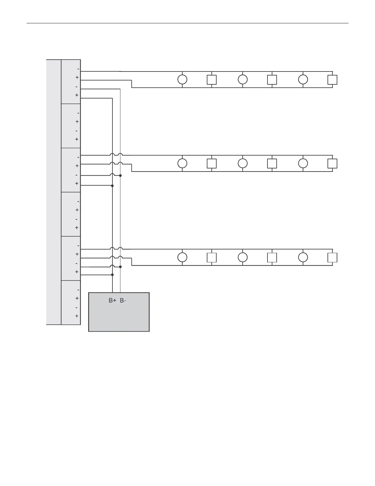
SLC Circuits with Isolators NFPA Style 4 SLC Using Isolator Modules
Each of the six circuits on ISO-6 functions the same way as ISO-X (discussed earlier). However, ISO-6 cannot accept two wires at one
pin. Wire Style 4 SLC loops as shown in Figure 5.5.
SLC Loop
Isolated Branch of SLC
Isolator 1Isolator 2Isolator 3Isolator 4Isolator 5Isolator 6
ISO-6
Six Fault
Isolator
Module
Fire Alarm Control Panel
Isolated Branch of SLC
Isolated Branch of SLC
Out -
Out +
In -
In +
SLC-style4iso-6.wmf
Figure 5.5 NFPA Style 4 SLC Using the ISO-6 Six Fault Isolator Module
 Loading...


