22 Notifier SLC Wiring Manual — P/N 51253:U5 12/20/2017
Section 3: Shielded Wire Termination
3.1 Overview
This section shows the proper termination of the shield, if used.
Shielding of the SLC is recommended for use with the AFP-100, AFP-200, AFP-300/400, LIB-200, and AIM-200. Proper termination of
the shield depends on the type of conduit used:
• Section 3.2, “No Conduit”.
• Section 3.3, “Full Conduit” (Canadian requirement).
• Section 3.4, “Partial Conduit”.
Shielding of the SLC is not recommended for use with the NFS-320, NFS-320SYS, NFS2-640, NFS-640, NFS2-3030, NFS-3030,
LCM-320, LEM-320, LIB-200A or LIB-400. If twisted-shielded wire is used in one of these installations, use a floating shield to termi-
nate the wire as shown in Section 3.5, “Floating Shield”, on page 23.
Use of good wiring practice consistent with local electrical codes is expected.
3.2 No Conduit
For use with the AFP-100, AFP-200, AFP-300/400, LIB-200, and AIM-200 only
Scrape the paint on the cabinet to bare metal to provide a good electrical connection. Fold the foil and drain wire back over the cable
jacket. Slide the cable into the connector clamp and secure. The drain wire should be connected to the connector screw. Do not allow the
shield drain wire or foil to enter the system cabinet.
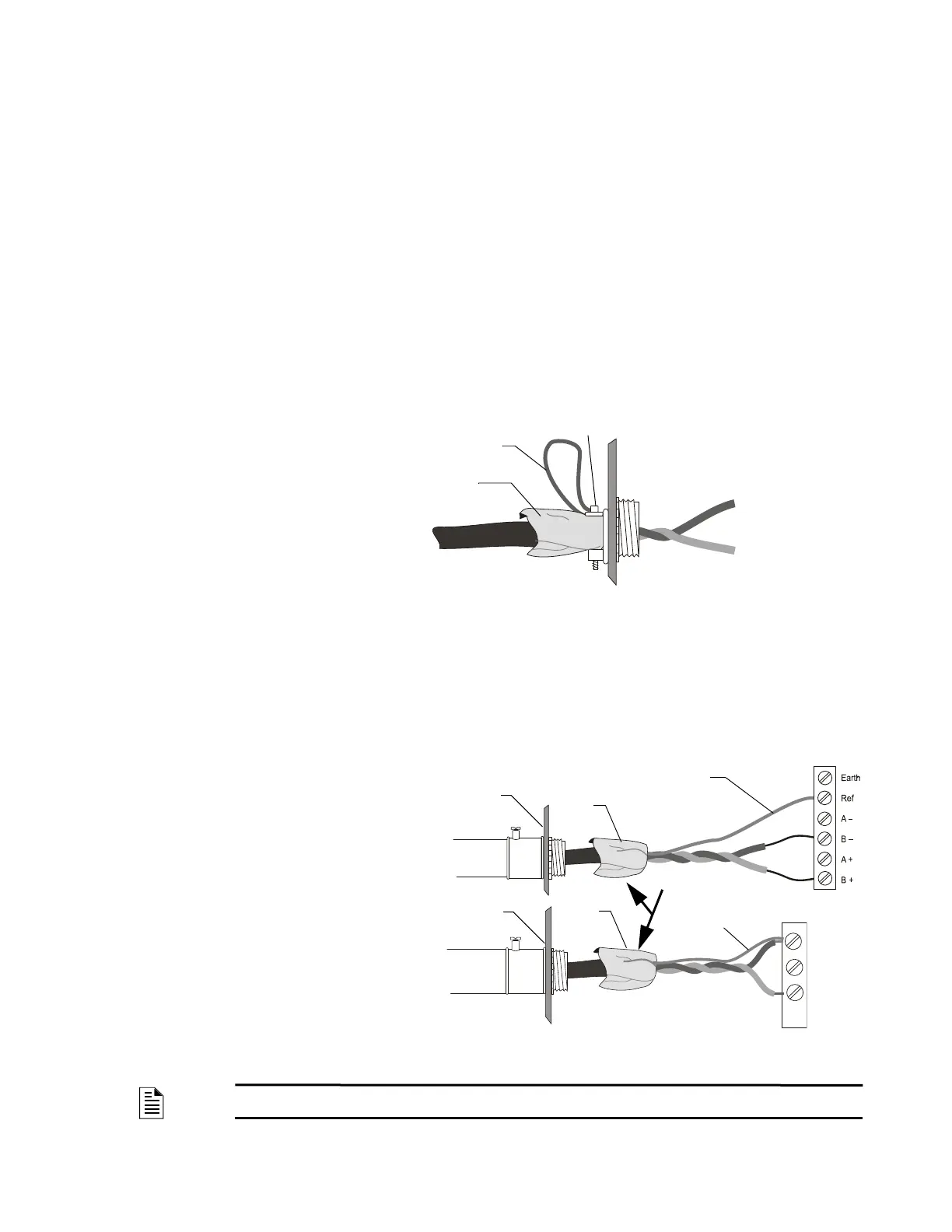
3.3 Full Conduit
For use with the AFP-100, AFP-200, AFP-300/400, LIB-200, and AIM-200 only
Connect the metal conduit to the cabinet by using the proper connector. Feed the shielded wire through the conduit, into the control box.
The shield drain wire must be connected to the “reference” or “shield” terminal on the SLC terminal block, or connected to the negative
side of the loop if there is no “reference” or “shield” terminal on the SLC terminal block. Do not let the shield drain wire or the shield
foil touch the system cabinet or be connected to earth ground at any point.
Shield Drain Wire
SLC-swterm1.wmf
Cabinet
Foil
Connector Screw
Figure 3.1 Shield Termination – No Conduit
NOTE: For Style 6 or Style 7 SLC wiring, connect one end of the shield to the reference/negative side of the
respective channel.
Cabinet
Shield Drain Wire
Foil
Conduit
Example at right illustrates
shield drain wire connection
to an SLC terminal block with
a “reference” connection.
Example at right illustrates
shield drain wire connection
to an SLC terminal block
without a “reference” or
“shield” connection.
Shield Drain Wire
Foil
Cabinet
Conduit
+
–
Shield2.wmf, SLC-
Tape over foil.
Figure 3.2 Shield Termination – Full Conduit
 Loading...


