94 ST 800 Pressure Transmitter User’s Manual Revision 15
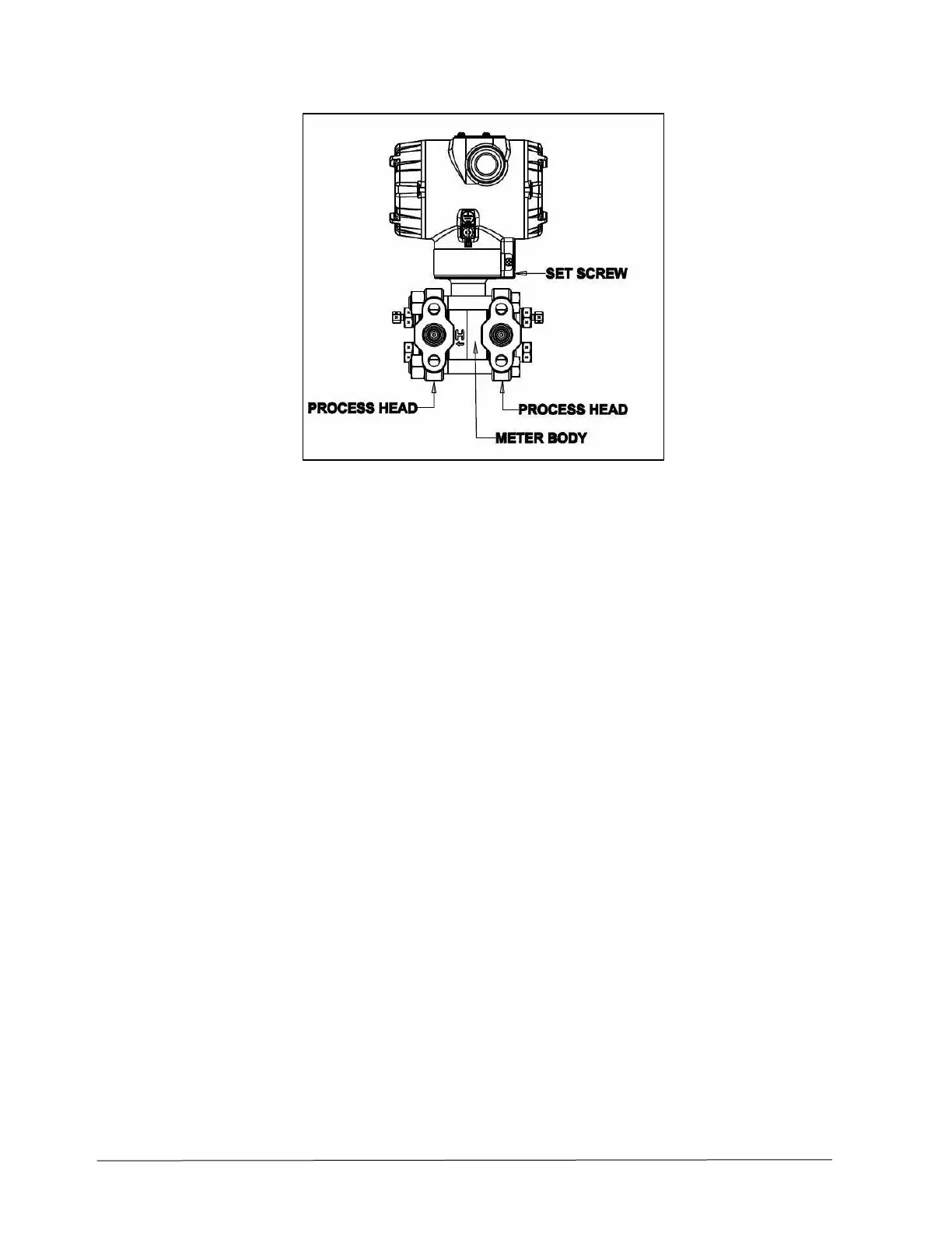
Figure 26 – Hardware Location to Remove the Meter Assembly
9. Carefully turn the complete meter body counterclockwise to unscrew it from the electronics
housing.
10. Remove the nuts from bolts that hold the process head(s) to the meter body.
11. Remove process heads and bolts.
12. Remove the gaskets or O-rings from the process heads.
13. Clean the interior of the process head(s) with a soft bristle brush and suitable solvent.
CAUTION: To prevent damage to the diaphragm in the meter body, use extreme care when handling or
placing the meter body on any surface. Carefully assemble gaskets or O- rings to the meter body. If installing
O-rings, lubricate with water or leave dry.
14. Coat threads on process head bolts with anti-seize compound such as “Never seize” or equivalent.
15. Refer to Figure 27. Apply Dow Corning #33 silicone grease to the meter body adapter O-ring and
carefully assemble the O-ring to the meter body. Assemble the process head(s) and bolts to the
new meter body. For now, make the bolts only finger-tight.
 Loading...


