89 ST 800 Pressure Transmitter User’s Manual Revision 15
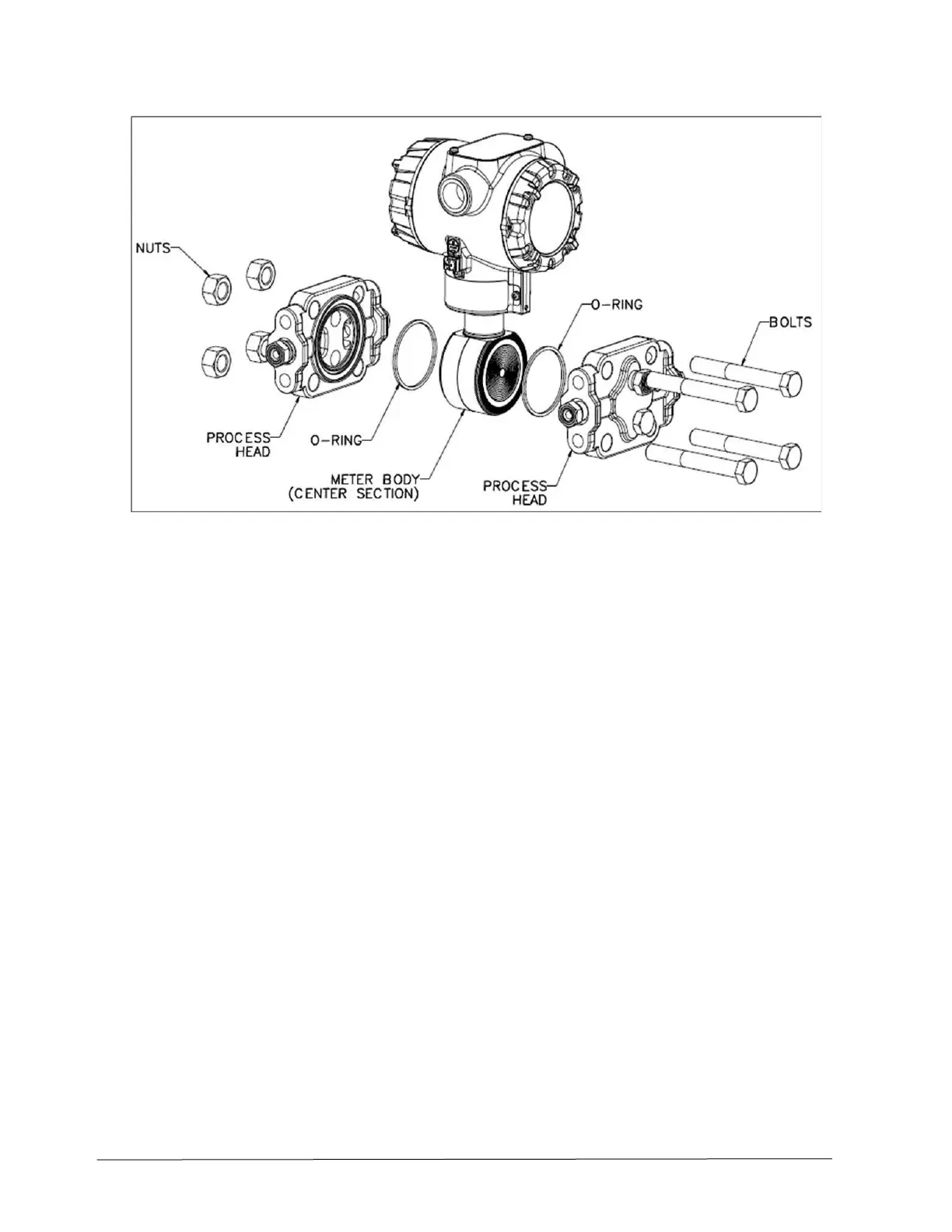
Figure 22 – DP Transmitter Head Disassembly
1. Close all valves to isolate the transmitter from the process.
2. Open the vent in the process head to drain fluid from the transmitter meter body, as necessary.
3. Remove the transmitter from the process.
4. Loosen the nuts in the sequence shown in Figure 22.
5. Remove the nuts from the bolts that hold the process head(s) to the meter body.
6. Remove the process heads and bolts.
7. Remove the gasket/ O-ring and clean the interior of the process head using a soft bristle brush and
an approved solvent.
8. Inspect the barrier diaphragm for signs of deterioration, corrosion, and distortion.
9. If the diaphragm is distorted contact Honeywell for assistance.
10. Install a new gasket/O-ring in each process head.
11. Coat threads on the process head bolts with a suitable anti-seize compound, such as “Never Seez”
or equivalent.
12. Using a torque wrench, gradually tighten the nuts in the sequence. Tighten head bolts in stages of
1/3-full torque, 2/3-full torque, and full torque. See Table 21 for torque requirements versus
transmitter type and model.
 Loading...


