1. Turn OFF transmitter power (Power removal is only required in accordance with area safety
approvals. Power removal is only required in Class 1 Div 1 Explosionproof and Class 1 Div 2
environments).
2. Loosen the end cap lock and unscrew the end cap from the electronics side of the
transmitter housing.
3. If equipped with a display module, carefully depress the two tabs on the sides of the display
module and pull it off.
4. If necessary, unplug the interface connector from the communication module. Do not discard
the connector.
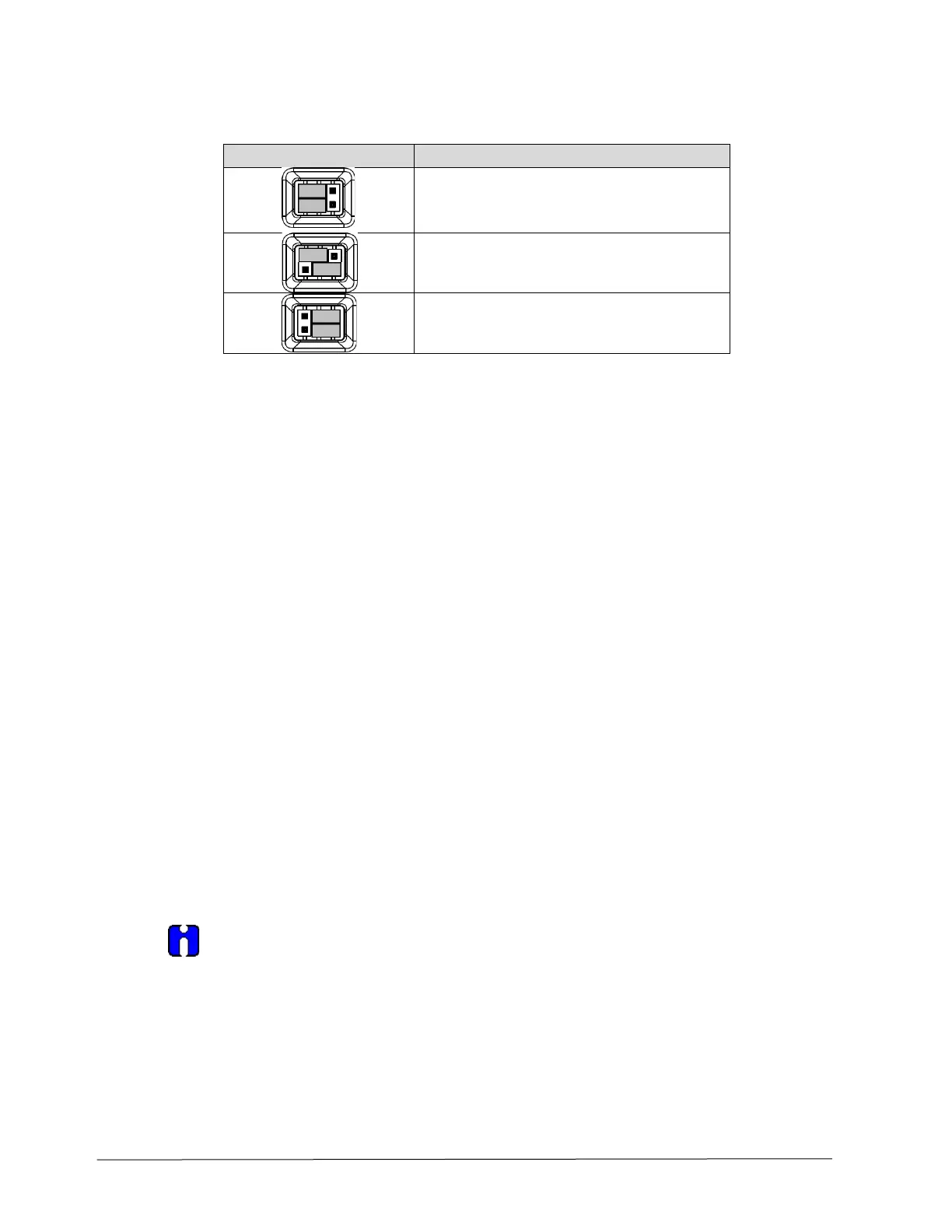
5. Set the Failsafe Jumper (top jumper) to the desired position (UP or DOWN). See
Table 18 and Table 19 for jumper positioning.
6. If applicable, re-install the display module as follows:
• Orient the display as desired.
• Install the Interface connector in the display module such that it will mate with the socket for
the display in the communication module.
• Carefully line up the display and snap it into place. Verify that the two tabs on the sides of
the display latch.
NOTE: Installing a display module into a powered transmitter may cause a temporary upset to
the loop output value.
Orient the display for proper viewing through the end cap window. You can rotate the
meter mounting orientation in 90
o
increments.
7. Restore transmitter power if removed.
 Loading...


