9 ST 800 Pressure Transmitter User’s Manual Revision 15
3.4.2 Mounting Dimensions
Refer to Honeywell drawing number 50049930 (Dual Head), 50049931 (In-Line), 50049932 (Flange
Mount) 50049933 (Extended Flange), and 50049934 (Remote Seal) for detailed dimensions. Abbreviated
overall dimensions are also shown on the Specification Sheets for the transmitter models. This section
assumes that the mounting dimensions have already been taken into account and the mounting area can
accommodate the transmitter.
3.4.3 Bracket Mounting Procedure
If you are using an optional bracket, start with Step 1. For an existing bracket, start with Step 2.
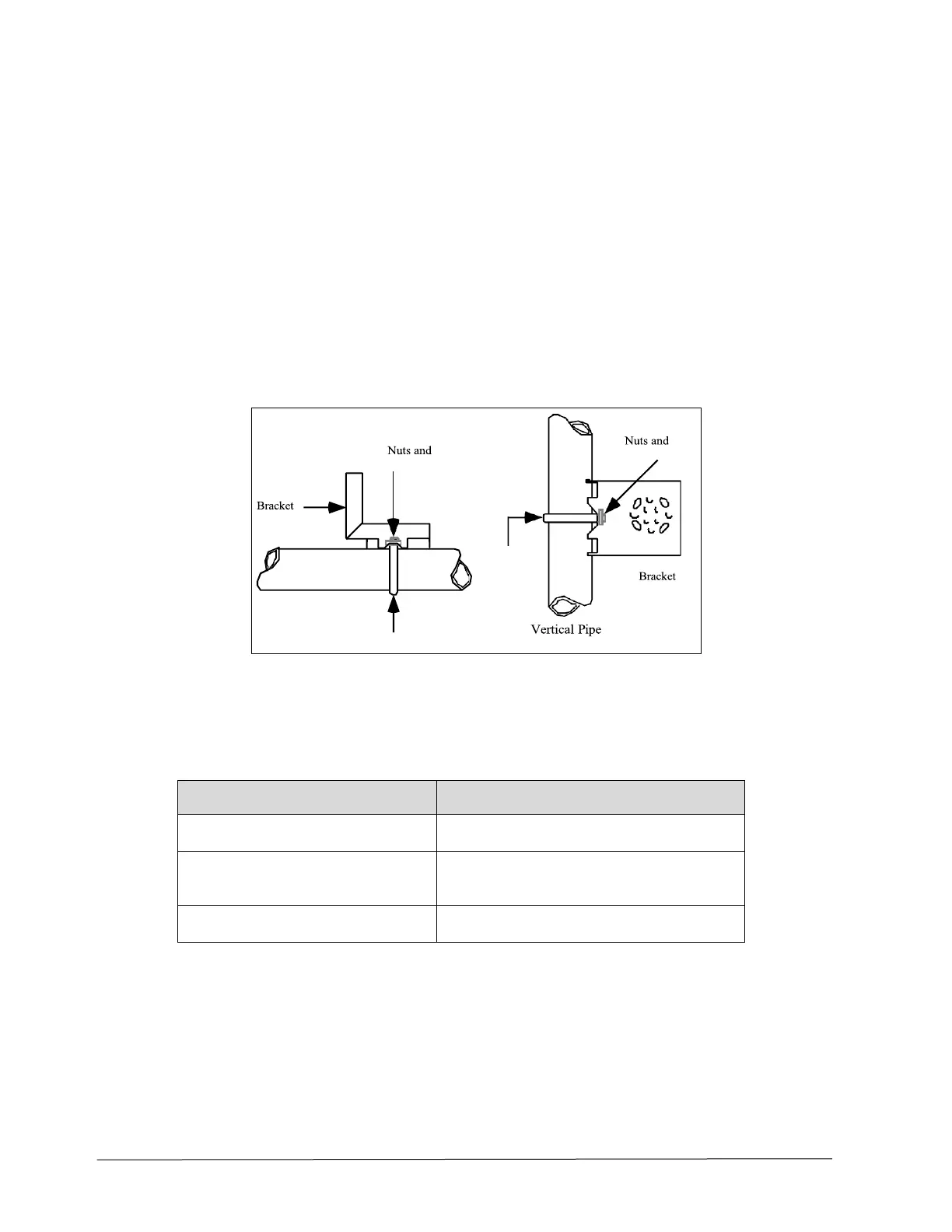
1. Refer to Figure 5. Position the bracket on a 2-inch (50.8 mm) horizontal or vertical pipe and
install a “U” bolt around the pipe and through the holes in the bracket. Secure the bracket with the
nuts and lock washers provided.
Figure 5 – Angle Mounting Bracket Secured to a Horizontal or Vertical Pipe
2. Align the appropriate mounting holes in the transmitter with the holes in the bracket. Use the
bolts and washers provided to secure the transmitter to the bracket; see the following variations.
 Loading...


