8 ST 800 Pressure Transmitter User’s Manual Revision 15
3.3 Display Installation Precautions
Temperature extremes can affect display quality. The display can become unreadable at temperature
extremes; however, this is only a temporary condition. The display will again be readable when
temperatures return to within operable limits.
The display update rate may increase at cold temperature extremes, but as with readability, normal
updating resumes when temperatures are within limits for full operability.
3.4 Mounting ST 800 SmartLine pressure transmitters
3.4.1 Summary
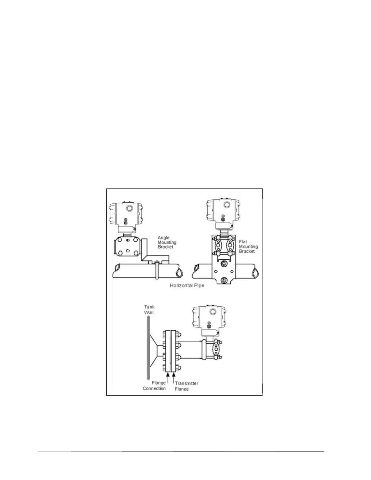
Transmitter models, except flush mounts and those with integral flanges, can be attached to a two-inch
(50 millimeter) vertical or horizontal pipe using Honeywell’s optional angle or flat mounting bracket;
alternately you can use your own bracket. Flush-mount models are attached directly to a process pipe or
tank by a one-inch weld nipple. Models with integral flanges are supported by the flange connection.
Figure 4 shows typical bracket-mounted and flange-mounted transmitter installations.
Figure 4 – Typical Bracket Mounted and Flange Mounted Installations
 Loading...


