28
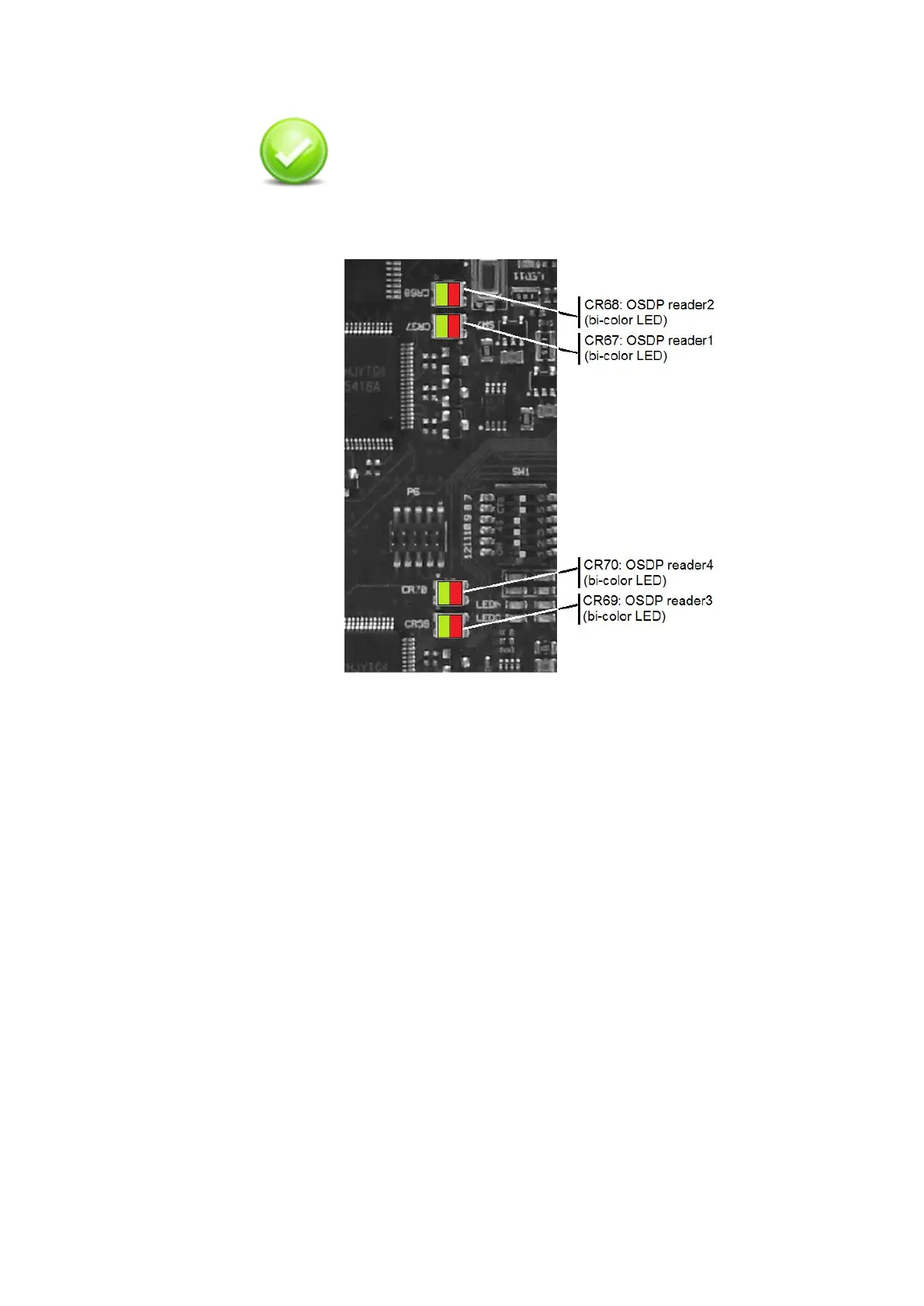
OSDP reader check: once the connection with the
reader is properly established and configured, the Multi
and the reader are switched on; the bi-color LED (Red
and Green) must blink regularly. Red color indicates
transmission where green color receiving.
Figure 12 - OSDP readers, communication LED positions
RS485 line length setting
On Multi device there is a series of switches used, when OSDP
readers are connected, to select RS-485 matched distance mode.
Multi supports biasing and end-of-line termination for the RS-485
network. Please refer chapter “Switches and LEDs” on page 61 for the
position of the switches.
For every reader there are two switches, one for Data A and one for
Data B that need to be set both in the same way:
• When switch is OFF (terminator resistor is not inserted) RS-485
allows the wiring of single-drop communication network of up to
15 m in length.
• When switch is ON (terminator resistor is inserted) RS-485
allows the wiring of single-drop communication network of up to
1200 m in length.
 Loading...