47
7. If you are using VMA-07 wire the input used to cut the
POE/POE+ internal power supply (see for details: Connection
of the emergency input to VMA-07 on page 55).
Setting up Plug-in jumper
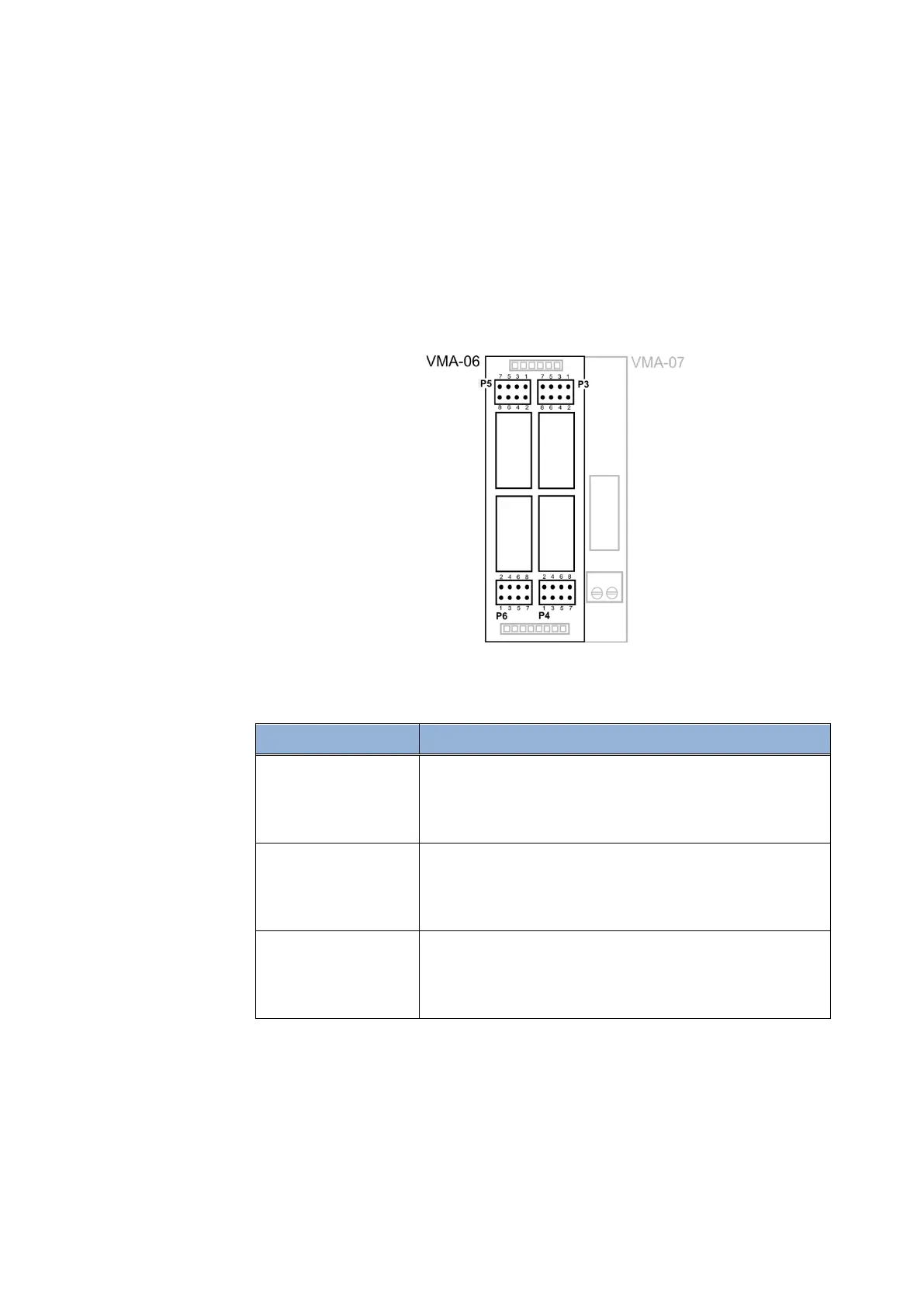
On VMA-06 and VMA-07 each jumpers block is relating to a single
output; the below picture and table give the match between jumpers
block and outputs based on the position of the plug-in on the board.
Figure 18 - Jumpers blocks on plugs-in
Plug-in position Outputs match
P5 – Fixed output1
P3 – Fixed output2
P4 – Fixed output3
P6 – Fixed output4
P5 – Line3
P3 – Line4
P4 – Line5
P6 – Line6
P5 – Line1
P3 – Line2
P4 – Line7
P6 – Line8
Table 5 - Matches between jumpers blocks and outputs
Specific position of jumpers on the jumper block is used to specify one
of the four modes in which the relay outputs can work:
• Dry contact normally open (default jumper setup)
 Loading...