Micro OCS Communications
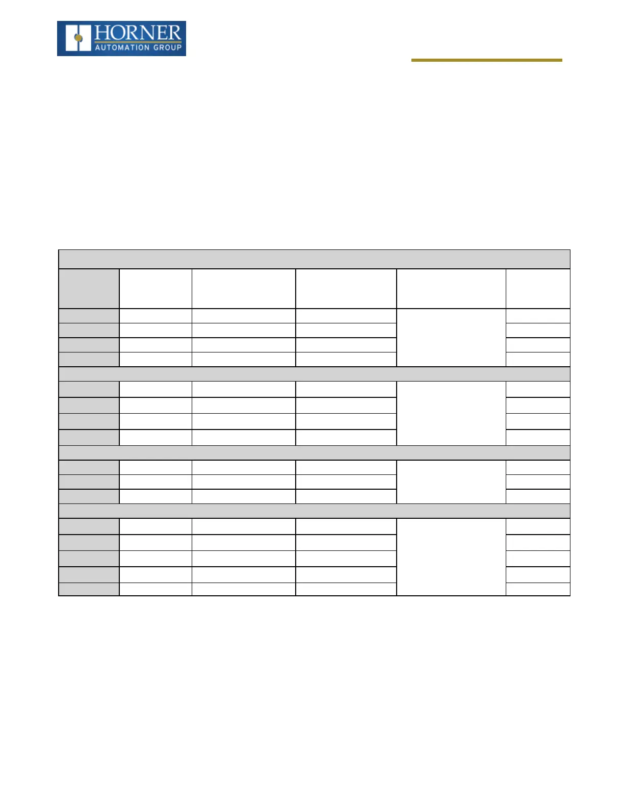
Modbus Addressing Table
To access the registers, a Modbus Master must be configured with the appropriate register type and offset. This is
usually accomplished with one of two methods:
Method 1: The first method uses Traditional Modbus References, in which the high digit represents the register
type, and the lower digits represent the register offset (starting with Register 1 for each type). Since only four
register types can be represented in this manner, Micro OCS controller Modbus Function Blocks pack several
register types into each Modbus register type. Starting addresses of each register type are shown in the Traditional
Modbus Reference column of the Mobus Table.
Method 2: The second method requires the Modbus Master to be configured with a specific Modbus Command and
Modbus Offset. The supported Modbus commands and the associated offsets are also illustrated in Modbus Table.
Micro OCS Controller Modbus Master Mapping
Reference
Maximum
Range
Trad. Modbus Refer-
ence
(5 Digits)
Expanded Modbus
Ref.
(6 Digits)
Modbus Command
(s)
Modbus Off-
set
%I1 1024 10001 010001
Read Input Status (2)
0
%IG1 256 13001 013001 3000
%S1 256 14001 014001 4000
%K1 10 15001 015001 5000
%Q1 1024 00001 000001
Read Coil Status (1)
Force Coil (5)
Force Multiple Coils
(15)
0
%M1 1024 03001 003001 3000
%T1 1024 06001 006001 6000
%QG1 256 09001 009001 9000
%AI1 256 30001 030001
Read Input Register
(4)
0
%AIG1 32 33001 033001 3000
%SR1 200 34001 034001 4000
%AQ1 256 40001 040001
Read Holding Register
(3)
Load Register (6)
Load Multiple
Registers (16)
0
%R1 2488 40513 040513 512
%R1 2048 43001 043001 3000
%AQG1 32 46001 046001 6000
%R1 5000 -- 410001 10000
Page 150 of 163



 To Next Page