High Speed I/O
Quadrature
Two HSC inputs are consumed for each of the two possible Quadrature counters. For example, selecting quad-
rature mode for HSC 1 will use HSC inputs 1 and 2, which correspond to A and B quadrature signals. Therefore,
HSC 1 and 3 may be configured for quadrature input. Alternately, HSC 3 may be configured to reset HSC1 (quad-
rature) count on a marker input
Quadrature mode works much like the totalizer except the accumulator will automatically increment or decrement
based on the rotation phase of the two inputs. See the following example for more details. Quadrature inputs are typ-
ically used for reporting the value of an encoder.
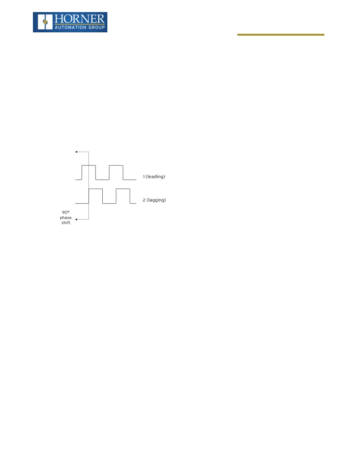
Two modes are available for quadrature that select whether the accumulator counts up or down when the phase of
input 1 leads input 2. Check your encoder’s documentation to determine the output form it uses or try both modes to
determine if the encoder counts up when expected.
Using the above waveforms and a HSC input configuration of “Quadrature” - “1 leads 2, count up,” the accumulator
will count up when 1 is rising and 2 is low, 1 is high and 2 is rising, 1 is falling and 2 is high, and when 1 is low and 2
is falling. This results in 4 counts per revolution. So in order to determine the number of cycles, the accumulator
would have to be divided by 4.
Three different options are available to reset (or set) the current count:
l
Configured Counts per Rev Value - When configuring the quadrature function, a value may be specified
under the Counts per Rev column. When rotation produces an increasing count, the quadrature accumulator
resets to zero on reaching the Counts per Rev count. Alternately, when rotation produces a decreasing
count, the quadrature accumulator is set to Counts per Rev – 1 on the count following zero. Specifying zero
for this value allows the totalizer to count through the full 32-bit range before resetting. For example, if your
encoder outputs 1024 counts per revolution, the value of 1024 can be entered into the configuration for
Counts per rev. This will result in a counter that produces counts in the range of 0 to 1023.
l
Ladder Control - Setting registers %Q17 or Q19 resets quadrature (HSC) 1 or quadrature (HSC) 3 (respect-
ively) with no additional configuration. Setting registers %Q18 or Q20 sets quadrature (HSC) 1 or quadrature
(HSC) 3 (respectively) to Counts per Rev – 1.
l
Direct Digital Input Control (HSC3) [Marker] - When HSC input 1 and 2 are used for quadrature inputs, an
additional choice of marker input becomes available for HSC input 3. The marker input is typically part of an
encoder or motion system that signals when a cycle of motion is complete. When the marker input is
triggered, the accumulator is reset to zero or to Counts per rev - 1 based on rotation direction. Marker reset
operation is enabled when HSC3 is configured for Marker type. Once selected, one of several modes is avail-
able for marker operation. These modes can be sub-divided into two groups of marker operation.
Asynchronous modes ignore the quadrature inputs and reset the quadrature accumulator to zero on the con-
figured edge (rising, falling or both). These are the most common settings used. When configuring, asynchronous
mode selections are prefixed with the word Async.
Page 87 of 163