General I/O Configuration
Relay Outputs
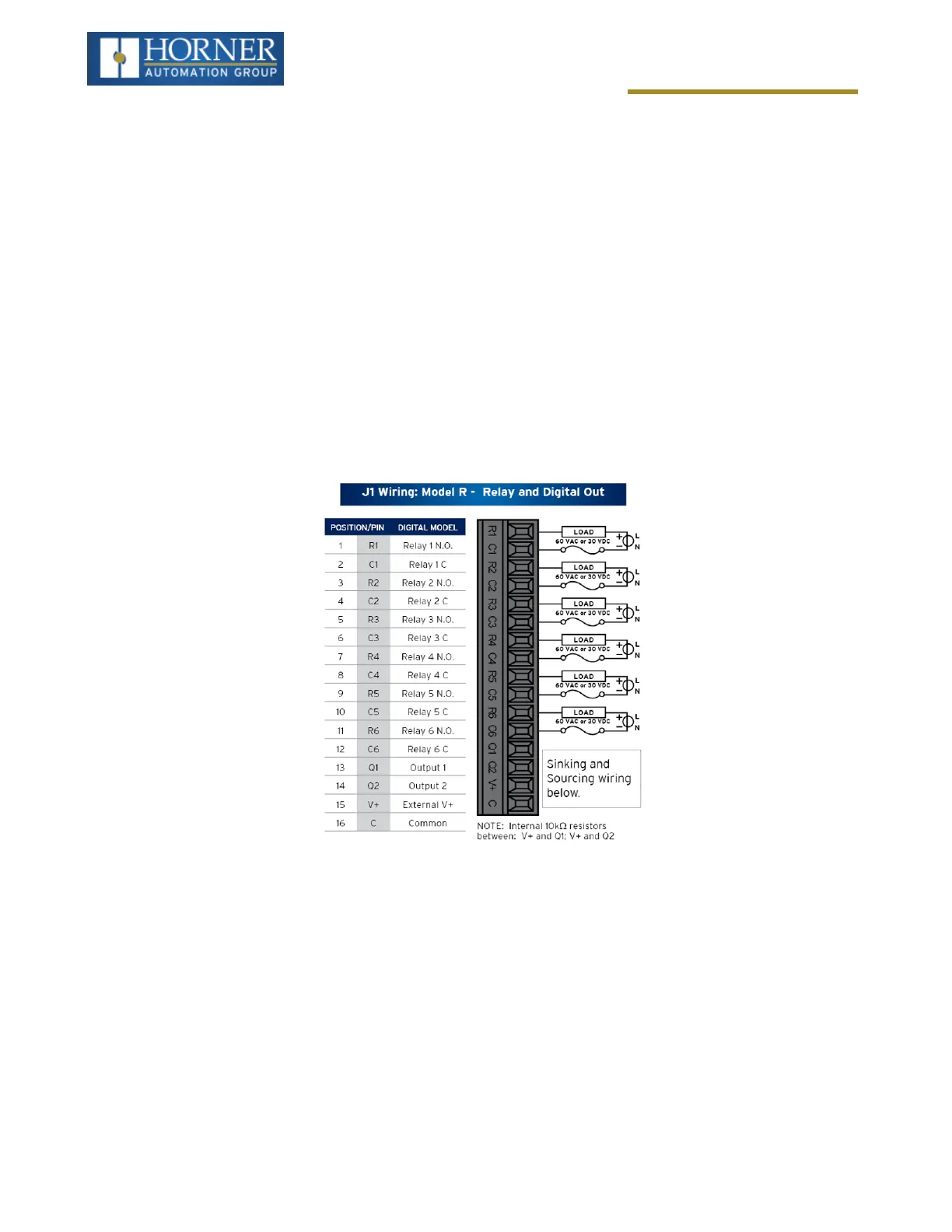
Relay outputs are designed to switch loads that typically have high voltage or current requirements or require the
isolation that relays provide. Relay outputs are not available on all controllers, see the datasheet. NOTE: The
design of the OCS does not require external coil power for the relays to function. The relays will activate anytime the
OCS is powered. There are several factors that should be considered when using relays:
l
Relay Life – Relays are mechanical devices that have a long but limited life. Typically, switching more cur-
rent limits the life of relays. Please check the data sheets at the end of this manual for expected relay life.
l
Current / Temperature De-Rating – Products containing relays often have total current limits based on the
ambient temperature of the application. Please see the product data sheet for current / temperature de-rating
information for relays.
l
Fusing – External fusing is generally required to protect the relays, devices and wiring from shorts or over-
loads.
WARNING: To protect the module and associated wiring from load faults, use external (5A) fuse(s) as shown.
Fuses of lower current or fusing for the entire system need to be in place to assure the maximum current rating of
the unit is not exceeded.
WARNING: Connecting high voltage to any I/O pin can cause high voltage to appear at other I/O pins.
Protection for Inductive Loads – Inductive loads can cause reverse currents when they turn off that can shorten
the life of relay contacts. Some protective measures must be determined by an engineer. Below are some recom-
mendations that will work for many applications. If there are additional questions on protection from inductive load,
consult Horner Technical Support.
n
DC Loads – General purpose diode (IN4004) in reverse bias across the load.
n
AC Load – MOV (Harris V140xxx for 120V, V275xx for 220V)
Output State on Controller Stop – When the controller is stopped the operation of each output is configurable.
The outputs can hold the state they were in before the controller stopped or they can go to a predetermined state.
By default, relay outputs turn off. For more information on stop state, refer to "Cscape Configuration" on page1.
Page 67 of 163