High Speed I/O
Totalize
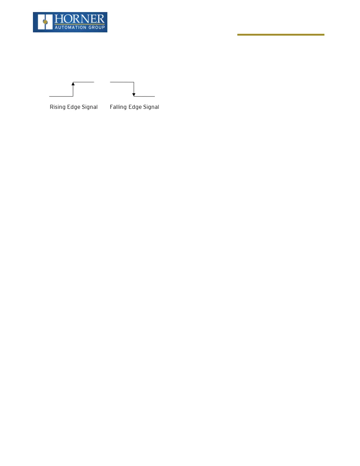
In totalize mode, the accumulator is simply incremented each time the input transitions in a specific direction. Total-
ize mode is configurable to specify the edge (rising or falling) on which the accumulator is incremented.
Three different options are available to reset the current count:
l
Configured reset value - When configuring the Totalize function, a value may be specified under the
Counts per Rev column. When the totalizer accumulator reaches this value - 1, the accumulator will reset to
zero on the next count. Specifying zero for this value allows the totalizer to count through the full 32-bit range
before resetting.
l
Ladder control - Setting registers %Q17-20 reset HSC1-4 (respectively) with no additional configuration.
When these registers are asserted, the associated totalizer accumulator is reset and held at zero (level sens-
itive).
l
Direct digital input control (HSC1 and HSC2 only) - HSC3 (%I11) and HSC4 (%I12) may be configured
as hardware digital reset signals for HSC1 and HSC2 (respectively). To enable these inputs as reset signals,
specify the type as Totalize Reset (NOTE: The corresponding Totalize HSC must be previously configured
before this option is available). The direct digital reset controls are edge sensitive with the edge polarity con-
figurable.
Maximum direct digital reset latency is 100μs.
The totalize function also supports an option which compares the current accumulator value with a supplied Preset
Value (PV), which is provided through a %AQ, and drives a physical digital output based on the that comparison.
l
This option (available for HSC1 and HSC2 only) drives Q1 or Q2 output point (respectively) once the asso-
ciated totalizer accumulator reaches (or exceeds) the PV value. To enable this function, the corresponding
PWM function output (Q1 or Q2) must be configured for HSCx Output.
NOTE: Q1 and Q2 are PWM function outputs that may be configured independently as one of the following: stand-
ard digital output, PWM, HSCx or stepper output.
Preset values may be modified during run-time. A preset value of zero disables (resets) the totalizer compares func-
tion output causing the output to remain low.
Page 85 of 163