Mechanical Installation
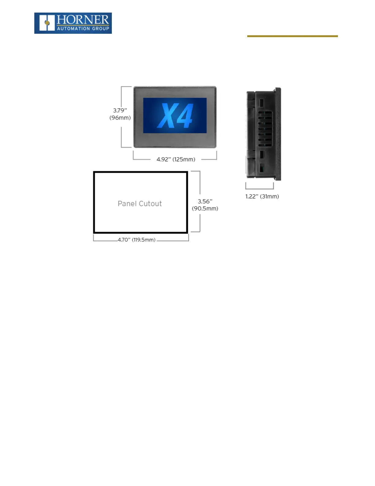
Dimensions
For installations requiring NEMA 4X liquid and dust protection, the panel cutout should be cut with a tolerance of
+0.5mm / -0mm.
Installation Procedure
l
This equipment is panel mounted and is meant to be installed in an enclosure suitable for the environment,
such that the back of the equipment is only accessible with the use of a tool.
l
This equipment is suitable for use in Class I, Division 2, Groups A, B, C and D; Class II, Division 2 Groups F
and G; and Class III Hazardous Locations or Non-Hazardous Locations only.
l
The X4 utilizes a clip installation method to ensure a robust and watertight seal to the enclosure. Follow the
steps below for the proper installation and operation of the unit.
1. Carefully locate an appropriate place to mount the X4. Be sure to leave enough room at the top of the unit for
insertion and removal of the microSD™ card.
2. Carefully cut the host panel per the diagram, creating a 90.5mm x 119.5mm with a tolerance of +/-0.5mm
opening into which the X4 is to be installed. If the opening is too large, water may leak into the enclosure,
potentially damaging the unit. If the opening is too small, the OCS may not fit through the hole without dam-
age.
3. Remove any burrs/sharp edges and ensure the panel is not warped in the cutting process.
4. Install and tighten the four mounting clips (provided in the box) until the gasket forms a tight seal. For stand-
ard composite mounting clips (included with product). NOTE: Torque rating is 2-3 in-lbs (0.23-0.34 Nm). For
optional metal mounting clips, use a torque rating of 4-8 in-lbs (0.45-0.90 Nm).
5. Connect communications cables to the serial port, USB ports, and CAN port as required.
Page 17 of 163