66
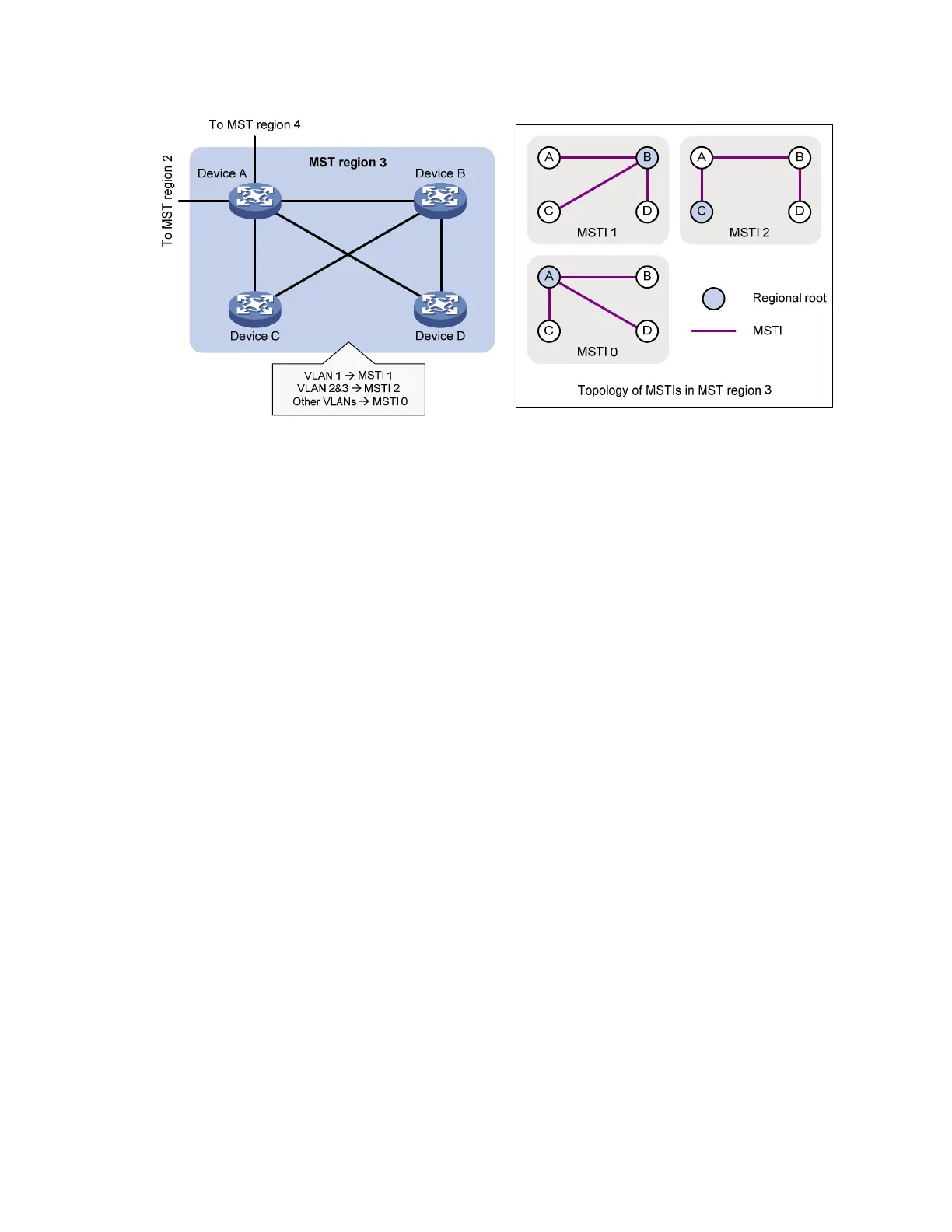
Figure 21 Network diagram and topology of MST region 3
As shown in Figure 20, a switched network comprises four MST regions, and each MST region comprises
four devices running MSTP. Figure 21 sh
ows the networking topology of MST region 3. This section
describes some basic concepts of MSTP.
MST region
An MST region consists of multiple devices in a switched network and the network segments among them.
All these devices have the following characteristics:
• MSTP-enabled
• Same region name
• Same VLAN-to-instance mapping configuration
• Same MSTP revision level configuration
• Physically linked with one another
Multiple MST regions can exist in a switched network. You can assign multiple devices to the same MST
region. In Figure 20,
the switched network comprises four MST regions, MST region 1 through MST
region 4, and all devices in each MST region have the same MST region configuration.
MSTI
MSTP can generate multiple spanning trees in an MST region, and each spanning tree is independent of
another and maps to the specific VLANs. Each spanning tree is referred to as a “multiple spanning tree
instance (MSTI).”
In Figure 21, f
or example, MST region 3 comprises three MSTIs, MSTI 1, MSTI 2, and MSTI 0.
VLAN-to-instance mapping table
As an attribute of an MST region, the VLAN-to-instance mapping table describes the mapping
relationships between VLANs and MSTIs.
In Figure 21, f
or example, the VLAN-to-instance mapping table of MST region 3 is: VLAN 1 to MSTI 1,
VLAN 2 and VLAN 3 to MSTI 2, and other VLANs to MSTI 0. MSTP achieves load balancing by means
of the VLAN-to-instance mapping table.

 Loading...


