84
Destination/mask Protocol Preference Cost Interface
0x010000/8 STATIC 10 0 Fc1/0/2
0x020000/8 STATIC 10 0 Fc1/0/2
0xfffc03/24 DIRECT 0 0 InLoop0
0xfffffa/24 DIRECT 0 0 InLoop0
0xfffffc/24 DIRECT 0 0 InLoop0
0xfffffd/24 DIRECT 0 0 InLoop0
# FCping Switch C from Switch A.
[SwitchA-vsan1] fcping fcid fffc03 vsan 1
FCPING fcid 0xfffc03: 128 data bytes, press CTRL_C to break
Reply from 0xfffc03: bytes = 128 time = 23 ms
Reply from 0xfffc03: bytes = 128 time = 9 ms
Reply from 0xfffc03: bytes = 128 time = 19 ms
Reply from 0xfffc03: bytes = 128 time = 14 ms
Reply from 0xfffc03: bytes = 128 time = 25 ms
--- 0xfffc03 fcping statistics ---
5 packet(s) transmitted
5 packet(s) received
0.00% packet loss
round-trip min/avg/max = 9/18/25 ms
The output shows that Switch A can reach Switch C.
Static FC routing configuration example by using VFC
interfaces
Network requirements
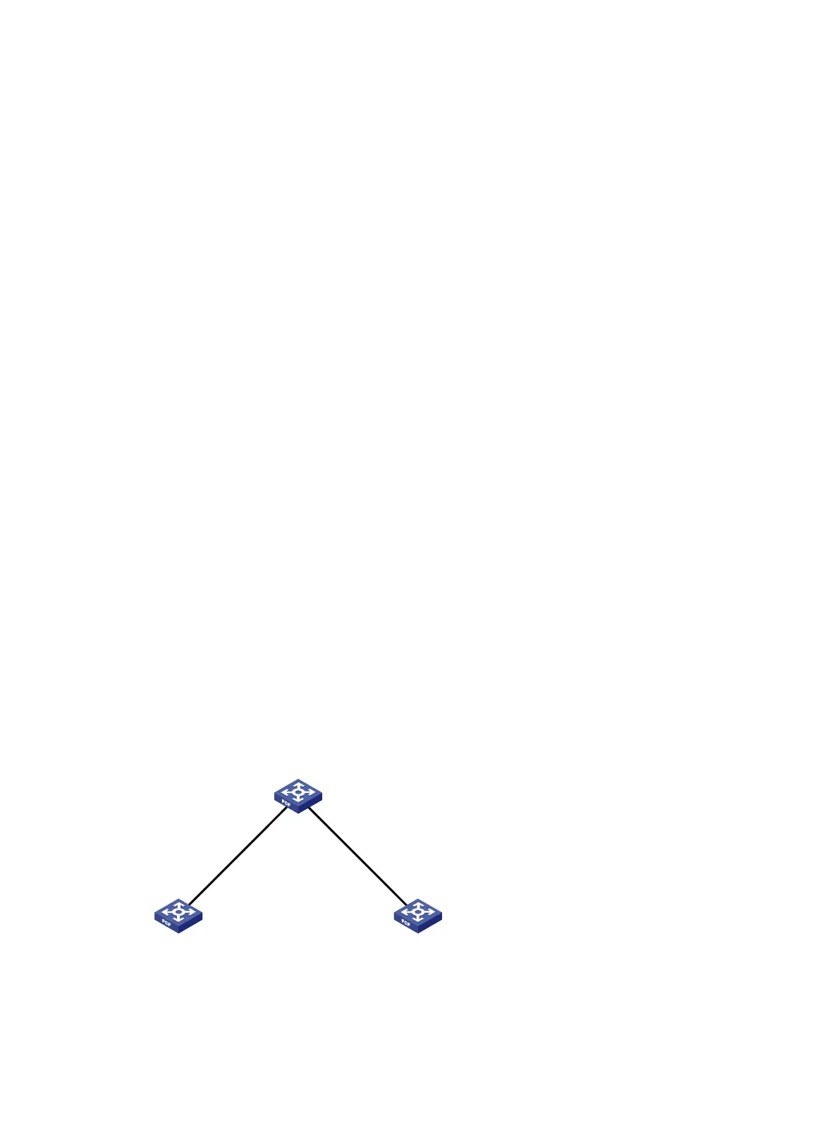
The fabric comprises three switches, Switch A, B, and C.
Configure static routes to enable any two FC switches to communicate with each other.
Figure 28 Network diagram
Configuration procedure
1. Configure Switch A:
Switch B
Switch A
VFC1
XGE1/0/1
Switch C
Domain ID: 1 Domain ID: 3
Domain ID: 2
VFC1
XGE1/0/1
VFC2
XGE1/0/2
VFC2
XGE1/0/2
 Loading...


