163
{ Switch A can reach Switch B.
{ Switch B cannot reach Switch C.
Verifying the configuration
# Use the display fc routing-table command on Switch B to verify that there is not a route to Switch C.
(Details not shown.)
FC tracert configuration example by using VFC interfaces
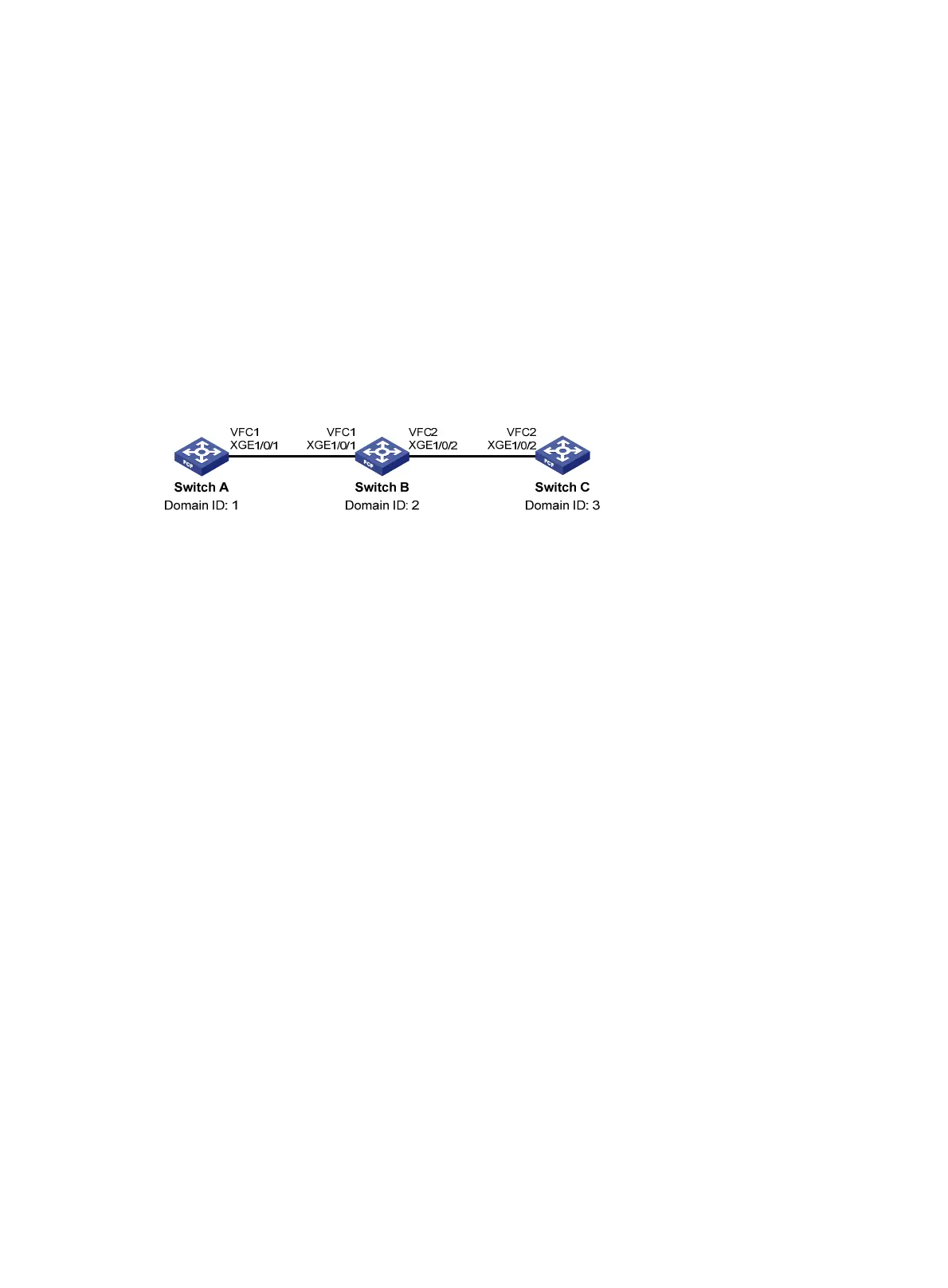
Network requirements
As shown in Figure 46, detect bidirectional routing information between Switch A and Switch C, and
identify the faulty node (if any).
Figure 46 Network diagram
Configuration procedure
1. Configure Switch A:
# Configure the switch to operate in advanced mode. (Skip this step if the switch is operating in
advanced mode.)
<SwitchA> system-view
[SwitchA] system-working-mode advance
Do you want to change the system working mode? [Y/N]:y
The system working mode is changed, please save the configuration and reboot the
system to make it effective.
# Save the configuration.
[SwitchA] save
The current configuration will be written to the device. Are you sure? [Y/N]:y
Please input the file name(*.cfg)[flash:/startup.cfg]
(To leave the existing filename unchanged, press the enter key):
Validating file. Please wait...
Saved the current configuration to mainboard device successfully.
[SwitchA] quit
# Reboot the switch.
<SwitchA> reboot
Start to check configuration with next startup configuration file, please
wait.........DONE!
This command will reboot the device. Continue? [Y/N]:y
Now rebooting, please wait...
# Configure the switch to operate in FCF mode.
<SwitchA> system-view
[SwitchA] fcoe-mode fcf
# Enable the fabric configuration feature in VSAN 1.

 Loading...


