11
As shown in Figure 11, the NPV switch resides between nodes and the core switch on the edge of the
fabric. The core switch is a switch operating in FCF mode. The NPV switch is connected to the nodes
through its F_Ports and to the core switch through its NP_Port. The NPV switch forwards traffic from its
connected nodes to the core switch.
The NPV switch appears as an FCF switch to nodes and as a node to the core switch.
For more information about NPV, see "Configuring NPV."
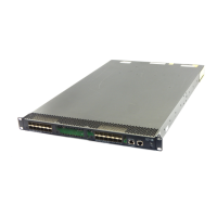
Transit mode
FCoE supports FC SANs built on lossless Ethernet networks, and allows Transit switches to be added
between FCF switches and ENodes. Figure 12
shows a scenario where ENodes are connected to FCF
switches through a Transit switch.
Figure 12 Transit network diagram
Ethernet interfaces on a Transit switch can operate in ENode mode or FCF mode.
• An Ethernet interface connected to an ENode must be configured to operate in ENode mode.
• An Ethernet interface connected to an FCF switch must be configured to operate in FCF mode.
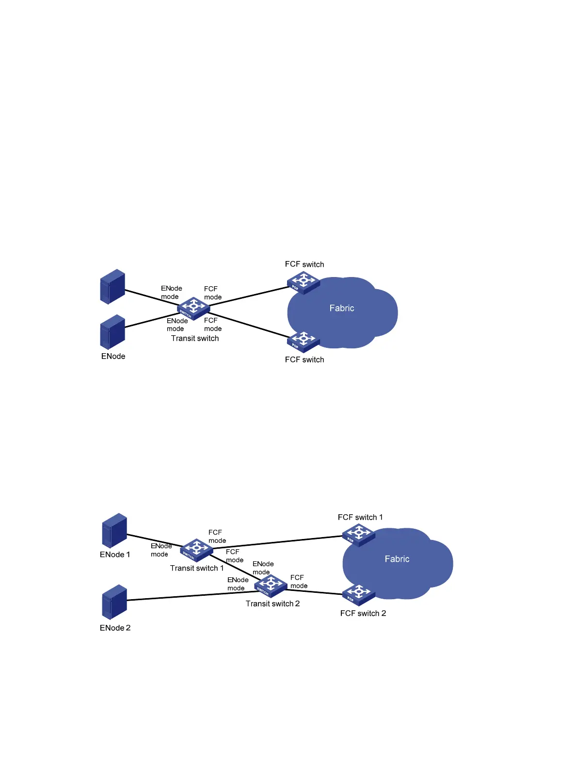
When Transit switches are interconnected, you must configure Ethernet interfaces to operate in the
correct modes. As shown in Figure 13,
ENode 2 can register with only FCF switch 2. To register ENode
2 with FCF switch 1, you must swap the operating modes of the Ethernet interfaces that connect the two
Transit switches.
Figure 13 Transit cascading network diagram
Figure 14 shows a network scenario where both Transit and NPV switches are present.
 Loading...


