211
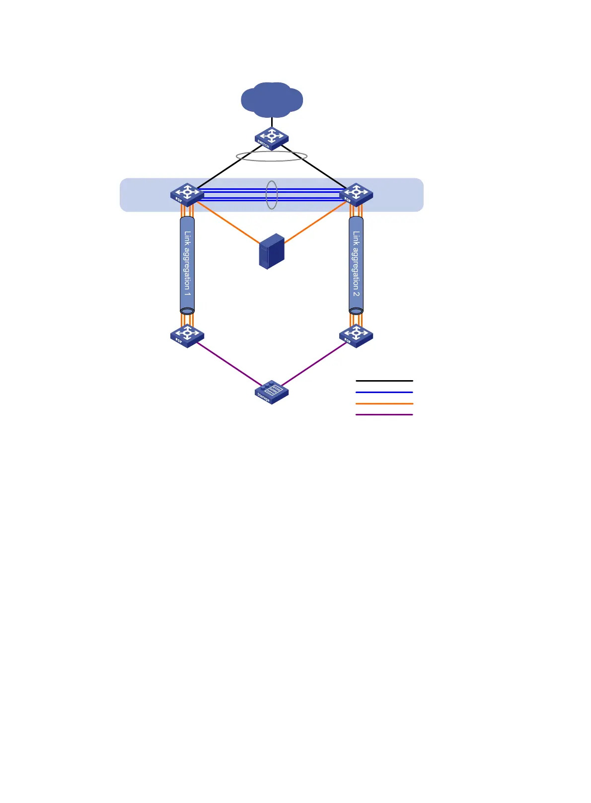
Figure 50 Network diagram
Requirements analysis
To meet the network requirements, perform the following tasks:
• To uniformly manage Switch A and Switch B and implement backup between them, configure
Switch A and Switch B to form an IRF fabric, with Switch A as the master device. The IRF fabric
operates at the access layer of the LAN and operates as the FCF switch of the SANs.
• Aggregate the four physical links connecting Switch A to Switch B into an IRF link, with ports
IRF-port 1/1 and IRF-port 2/2 at the two ends, respectively. Aggregate the links from the Ethernet
switch to Switch A and Switch B to form a multi-chassis aggregate link, Ethernet aggregate link 3.
• To transmit the storage traffic over lossless Ethernet links in the SANs, HP recommends that you
perform the following tasks:
{ Configure DCBX, PFC in auto mode, and ETS on the Ethernet interfaces connecting the switches
to the server.
{ Enable PFC by force on the Ethernet interfaces connecting switches.
• To implement link backup between the server and the disk device, use two separate SANs to
provide connections between the server and the disk device. The two separate VSANs are as
follows:
{ One physical SAN is formed by the server, the IRF fabric, Switch C, and the disk device.
{ The other physical SAN is formed by the server, the IRF fabric, Switch D, and the disk device.
Ethernet
switch
LAN
FCF switch
FCF switchFCF switch
Disk device
Server
Ethernet link
IRF link
FCoE link
XGE1/0/10 XGE2/0/10
XGE1/0/1
VFC1
XGE2/0/1
VFC2
XGE1/0/1 XGE1/0/1
FC1/0/1 FC1/0/1
XGE1/0/5 to XGE1/0/8
VFC10
XGE1/0/5 to XGE1/0/8
VFC10
XGE2/0/5 to XGE2/0/8
VFC11
XGE1/0/5 to XGE1/0/8
VFC10
Switch A
Switch DSwitch C
FCF switch
Switch B
FC link
 Loading...


