Removal and replacement procedures 55
11.
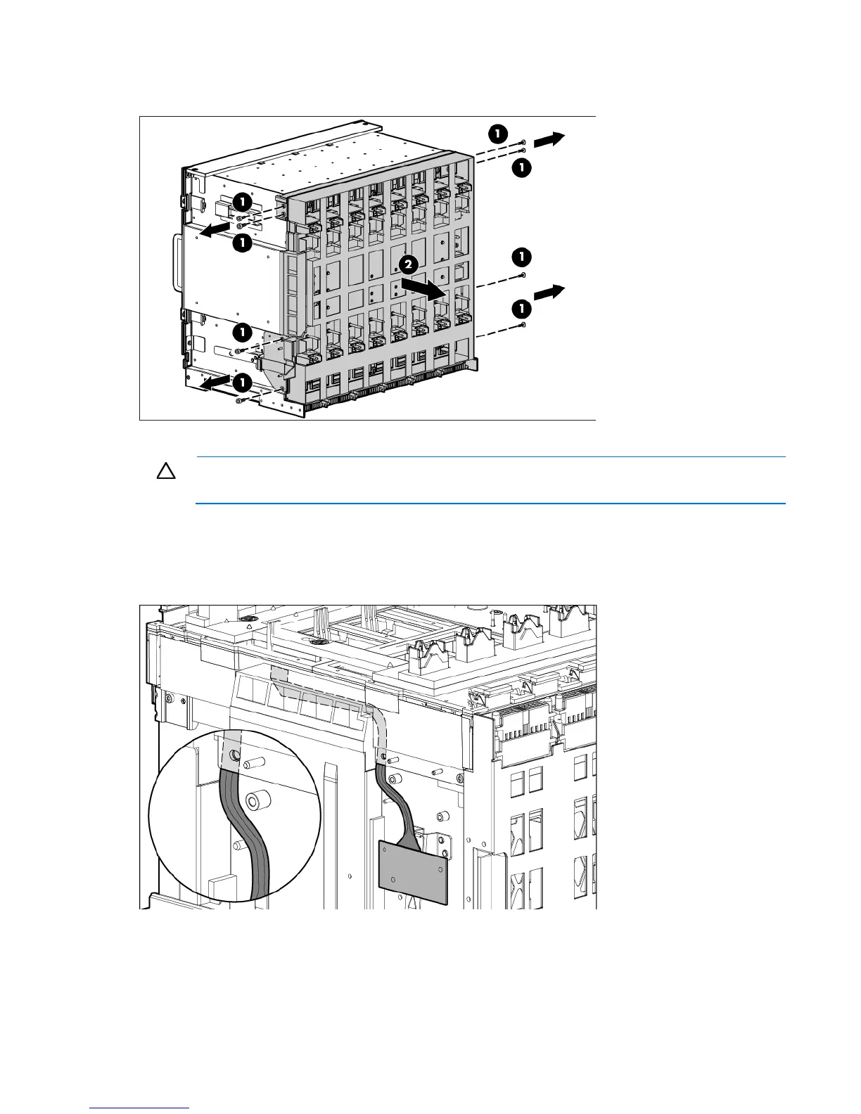
Remove the eight slotted T-15 Torx screws that secure the midplane assembly, and then remove the
midplane assembly from the rear cage.
To replace the midplane assembly, reverse the removal procedure.
CAUTION: The LCD cable must be correctly routed for proper operation.
To route the LCD cable:
1. When installing the midplane assembly onto the rear cage assembly, ensure the LCD cable is routed
behind the interconnect module rubber boot and through the sheet-metal gaps. Route the cable as
shown in the following figure.

 Loading...


