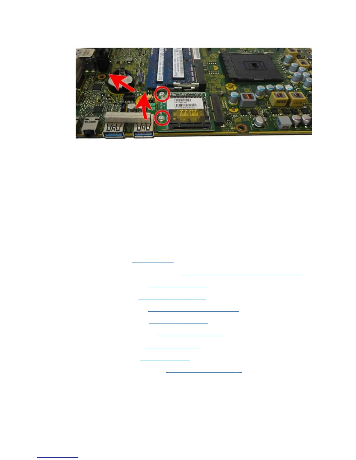
14. Lift the board to a 45-degree angle, and then pull it away to remove it from the socket (2).
To install the card reader board, reverse the removal procedures.
Front bezel and display panel
The front bezel is located on the front of the computer and is secured to the main system frame with 15 Torx
screws.
Replacement bezels include the webcam shutter and capacitive sensor board. On models that do not include
a webcam, you must remove the shutter and install the webcam cover (Assembly kit) into the slot in which
the webcam would be installed.
Display panels require a backlight cable specific to the manufacturer. Make sure you use the backlight cable
packaged with the display panel.
To remove the front bezel:
1. Remove the stand (see
Stand on page 29).
2. Prepare the computer for disassembly (see
Preparing to disassemble the computer on page 27).
3. Remove the access panel (see
Access panel on page 33).
4. Remove the webcam (see
Webcam module on page 55).
5. Remove the optical drive (see
Replacing the optical drive on page 39).
6. Remove the top rear trim (see
Top rear trim on page 54).
7. Remove the lower rear panel (see
Lower rear panel on page 59).
8. Remove the side panels (see
Side panels on page 76).
9. Remove the speakers (see
Speakers on page 63).
10. Remove the power button board (see
Power button board on page 68).
11. Remove the Torx screws that secure the bezel to the main system frame assembly, as follows:
●
15 total screws:
ENWW Front bezel and display panel 85

 Loading...