16
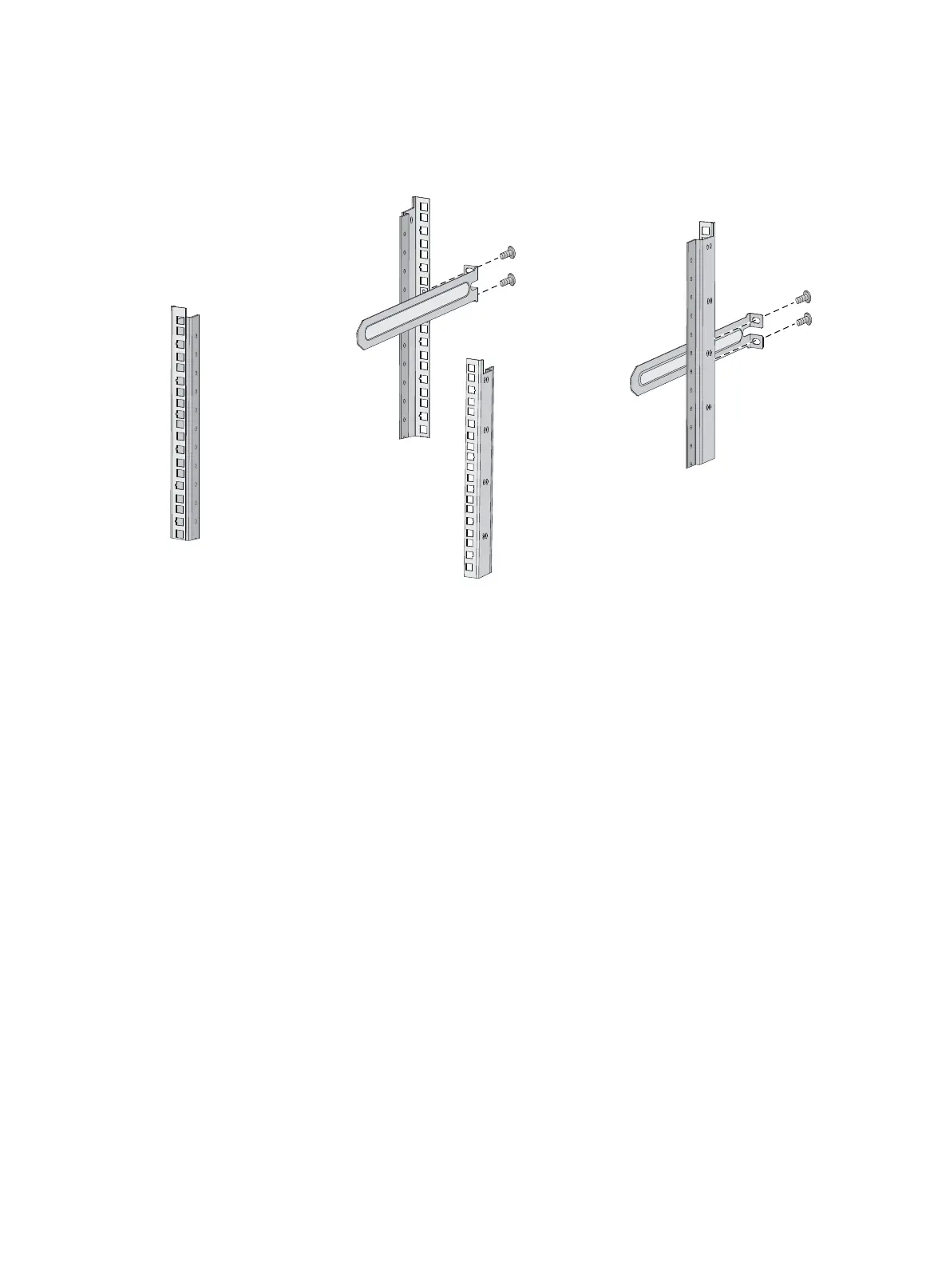
4. Repeat the preceding steps to attach the other slide rail to the rack post on the other side.
Keep the two slide rails at the same height so the slide rails can attach into the chassis rails.
Figure 17 Installing the 1U slide rails
Mounting the switch in the rack
This task requires two people.
To mount the switch in the rack:
1. Wear an ESD wrist strap and make sure it makes good skin contact and is reliably grounded.
2. Verify that the mounting brackets and chassis rails have been securely attached to the switch
chassis.
3. Verify that the slide rails have been correctly attached to the rear rack posts.
4. Install cage nuts (user-supplied) to the front rack posts and make sure they are at the same level as
the slide rails.
5. One person performs the following operations:
a. Supporting the bottom of the switch, aligns the chassis rails with the slide rails on the rack
posts.
b. Pushes the switch slowly to slide the chassis rails along the slide rails until the mounting
brackets are flush with the rack posts.
6. Another person uses screws (user-supplied) to attach the mounting brackets to the rack.
To secure the switch in the rack, make sure the front ends of the slide rails reach out of the chassis
rails.
The rack-mounting procedures are the same for the HP 5930-32 QSFP+/HP 5930-32 QSFP+ TAA and
HP 5930-2Slot+2QSFP+/HP 5930-2Slot+2QSFP+ TAA switches. The following figures use the HP
5930-2Slot+2QSFP+/HP 5930-2Slot+2QSFP+ TAA switch as an example.