46
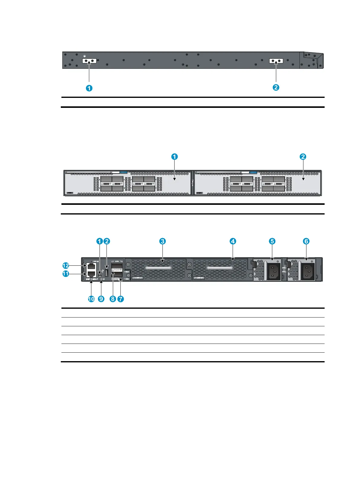
Figure 52 Left side panel
(1) Primary
roundin
point (2) Auxiliary
roundin
point 1
HP 5930-2Slot+2QSFP+/HP 5930-2Slot+2QSFP+ TAA
Figure 53 Front panel
(1) Interface module slot 1 (2) Interface module slot 2
Figure 54 Rear panel
(1) USB mini console port (2) USB port
(3) Fan tray slot 1
(4) Fan tray slot 2
(5) Power supply slot 1 (6) Power supply
slot 2
(7) QSFP+ port (8) QSFP+ port LED
(9) System status LED (SYS) (10) LINK
ACT LED for the mana
ement Ethernet port
(11) Mana
ement Ethernet port (12) Serial console port
The HP 5930-2Slot+2QSFP+/HP 5930-2Slot+2QSFP+ TAA switch comes with interface module slot 1
empty and interface module 2 installed with a filler panel. You can install one or two interface modules
for the switch as needed. In Figure 53, t
wo LSWM18QC interface modules are installed in the interface
module slots. For more information about installing and removing interface modules, see
"Installing/Removing an interface module."
The HP 5930-2Slot+2QSFP+/HP 5930-2Slot+2QSFP+ TAA switch comes with the two power supplies
empty and a filler panel as an accessory. You can install one or two power supplies for the switch as
needed. In Figure 54, t
wo 650W AC power supplies are installed in the power supply slots. For more
information about installing and removing power supplies, "Installing/removing a power supply."