11
Switch model Installation method Minimum distance Maximum distance
• HP 5930-4Slot
• HP 5930-4Slot TAA
Using provided mounting
brackets and chassis rails
518 mm (20.39 in) 888 mm (34.96 in)
Attaching the mounting brackets, chassis rails, and grounding
cable to the chassis
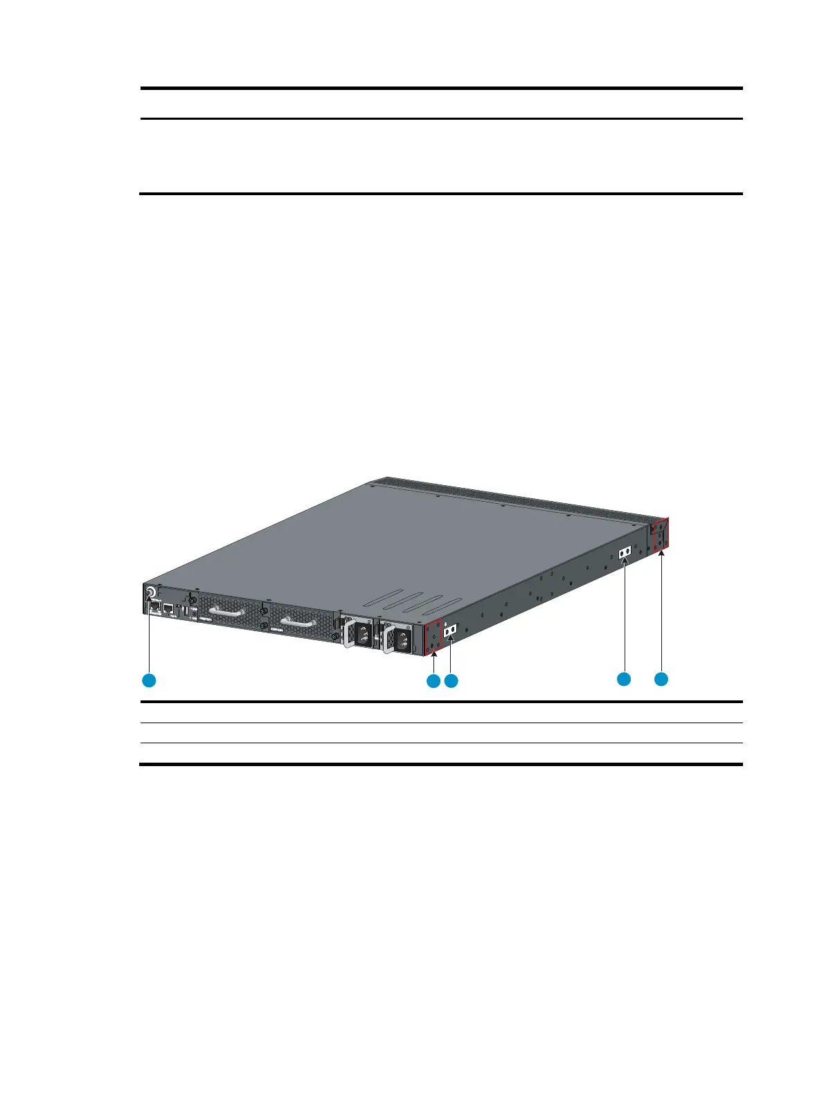
The switch has one mounting position near the network ports and one mounting position near the power
supplies for mounting brackets.
The HP 5930-32 QSFP+/HP 5930-32 QSFP+ TAA and HP 5930-4Slot/HP 5930-4Slot TAA switches
provide three grounding points: primary grounding point (with a grounding sign), auxiliary grounding
point 1, and auxiliary grounding point 2. The HP 5930-2Slot+2QSFP+/HP 5930-2Slot+2QSFP+ TAA
switch provides two grounding points: primary grounding point (with a grounding sign) and auxiliary
grounding point 1.
Figure 8 Mounting and grounding positions on the HP 5930-32 QSFP+/HP 5930-32 QSFP+ TAA switch
(1)
uxiliary
roundin
point 2 (2) Power
module-side mountin
position
(3) Primary grounding point (4) Auxiliary grounding point 1
(5) Network port-side mountin
position
1
2
3
4 5