12
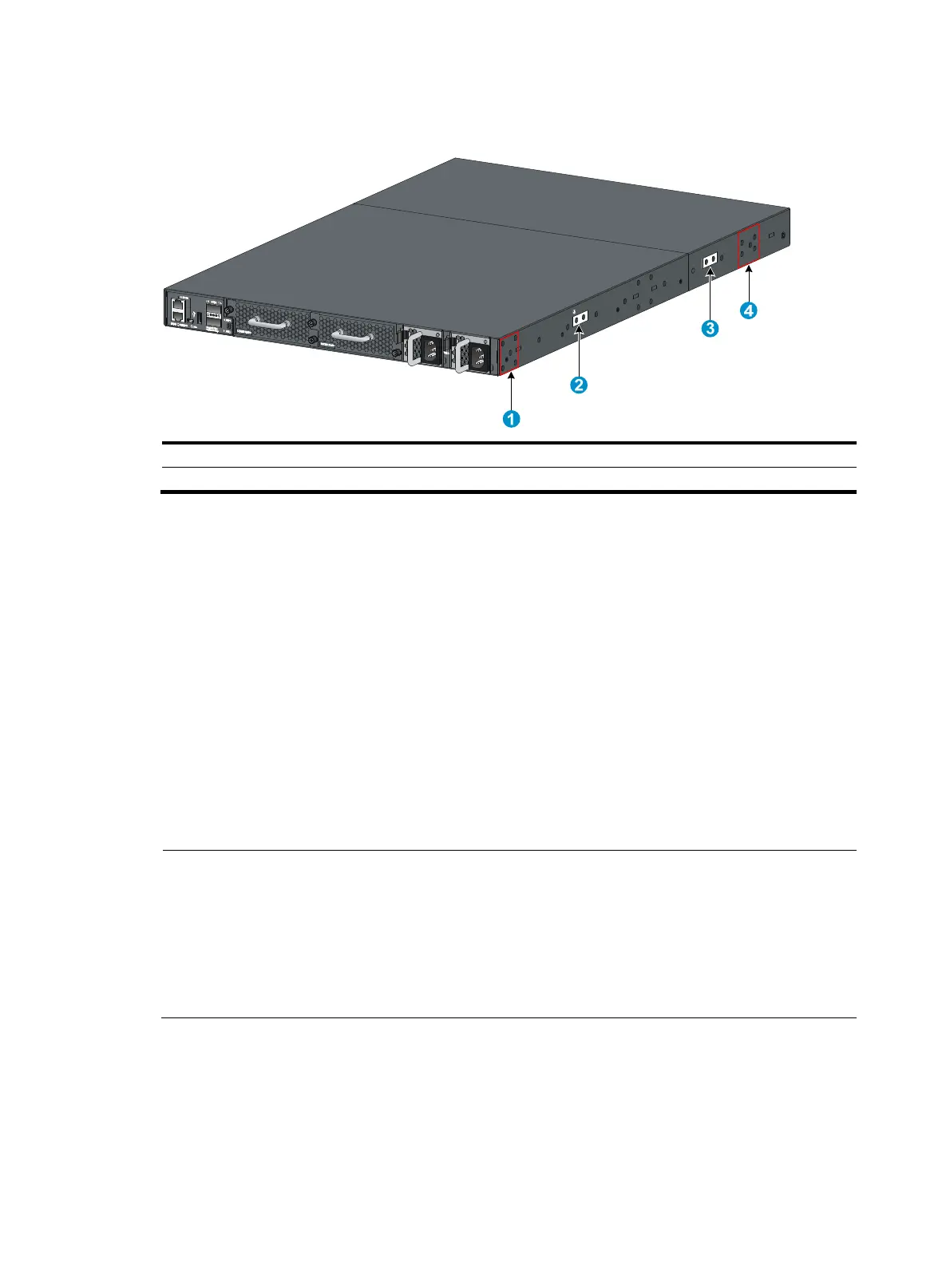
Figure 9 Mounting and grounding positions on the HP 5930-2Slot+2QSFP+/HP 5930-2Slot+2QSFP+
TAA switch
(1) Power module-side mountin
position
(2) Primary
roundin
point
(3) Auxiliary
roundin
point 1 (4) Network port-side mountin
position
Attaching the mounting brackets and chassis rails to the chassis
1. Align the mounting brackets with the screw holes in the chassis. Use M4 screws (provided) to
attach the mounting brackets to the chassis.
{ To install the mounting brackets at the power supply-side mounting position, see Figure
10, Figure 11, and Figure 12.
{ To install the mounting brackets at the network port-side mounting position, see Figure
13 , Figure 14, and Figure 15.
2. Align the
chassis rails with the rail mounting holes in the chassis:
{ If the mounting brackets are in the power supply-side mounting position, align the chassis rails
with the screw holes at the front of the side panels (see Figure 10, Figure 11, and Figure 12).
{ If the mounting brackets are in the network port-side mounting position, align the chassis rails
with the screw holes at the rear of the side panels (see Figure 13, Figure 14, and Figure 15).
3. Use M4 screws (provided) to attach the chassis rails to the chassis.
NOTE:
• Secure the mounting brackets and chassis rails to both sides of the chassis in the same way.
• To install the mounting brackets at the network port-side mounting position on the HP
5930-2Slot+2QSFP+/HP 5930-2Slot+2QSFP+ TAA and HP 5930-4Slot/HP 5930-4Slot TAA switches,
use the four screw holes nearest to the network port side. To install the mounting brackets at the power
supply-side mounting position on the HP 5930-2Slot+2QSFP+/HP 5930-2Slot+2QSFP+ TAA and HP
5930-4Slot/HP 5930-4Slot TAA switches, use the four screw holes nearest to the power supply side.