45
Appendix A Chassis views and technical
specifications
Chassis views
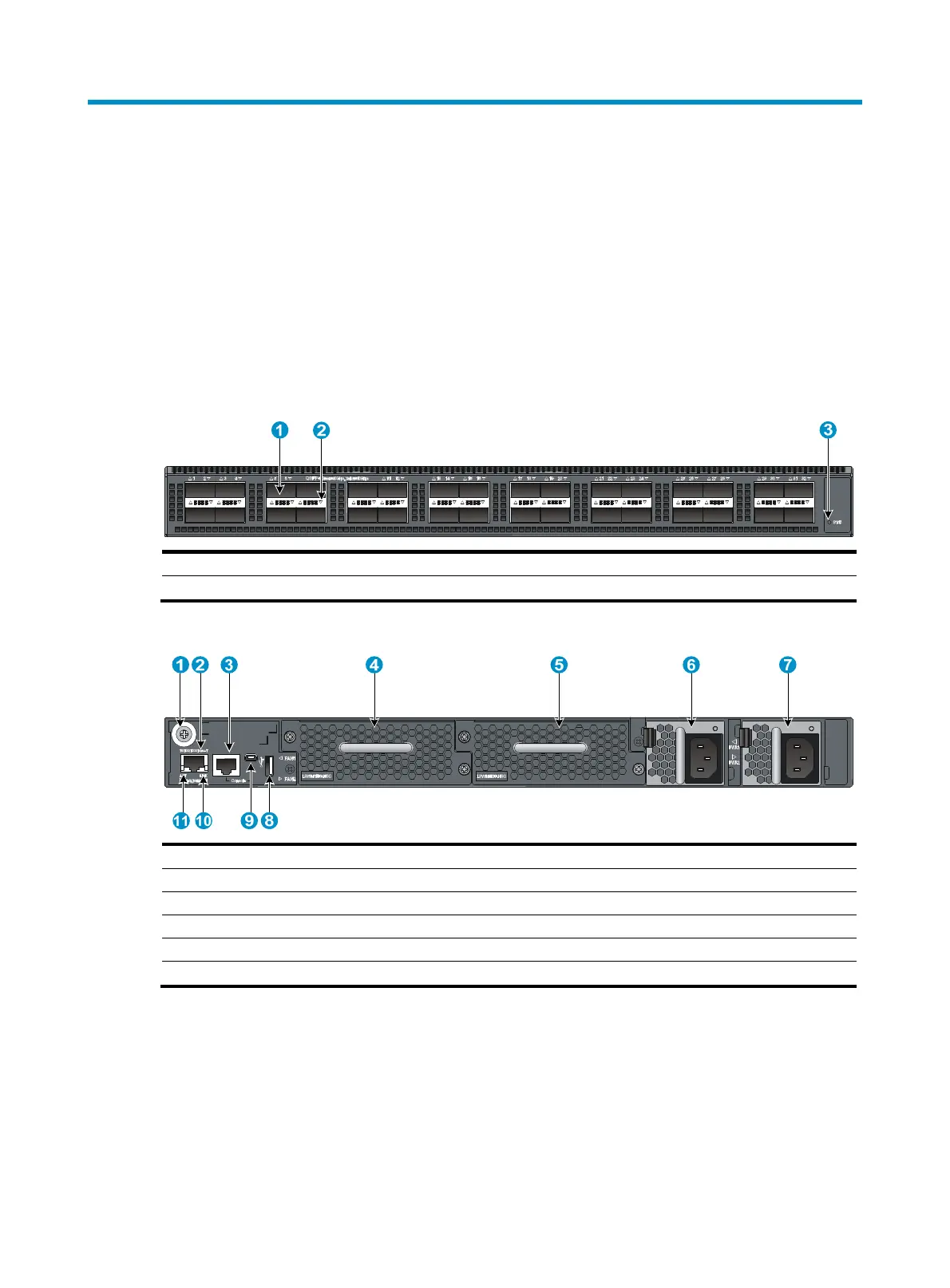
HP 5930-32 QSFP+/HP 5930-32 QSFP+ TAA
Figure 50 Front panel
(1) QSFP+ port (2) QSFP+ port LED
(3) System status LED (SYS)
Figure 51 Rear panel
(1) Grounding screw (auxiliary grounding point 2) (2) Management Ethernet port
(3) Serial console port (4) Fan tray slot 1
(5) Fan tray slot 2
(6) Power supply
slot 1
(7) Power supply slot 2 (8) USB port
(9) USB mini console port (10) LINK LED for the mana
ement Ethernet port
(11)
CT LED for the mana
ement Ethernet port
The HP 5930-32 QSFP+/HP 5930-32 QSFP+ TAA switch comes with the two power supply slots empty
and a filler panel as an accessory. You can install one or two power supplies for the switch as needed.
In Figure 51, t
wo 650W AC power supplies are installed in the power supply slots. For more information
about installing and removing power supplies, see "Installing/removing a power supply."
T
he HP 5930-32 QSFP+/HP 5930-32 QSFP+ TAA switch comes with the two fan tray slots empty. You
must install two fan trays of the same model for the switch. In Figure 51, t
wo LSWM1HFANSC fan trays
are installed in the fan tray slots. For more information about installing and removing fan trays, see
"Installing/removing a fan tray."