Component Identifications
4-4 HP ProLiant DL320 Generation 3 Server Maintenance and Service Guide
System Board Components
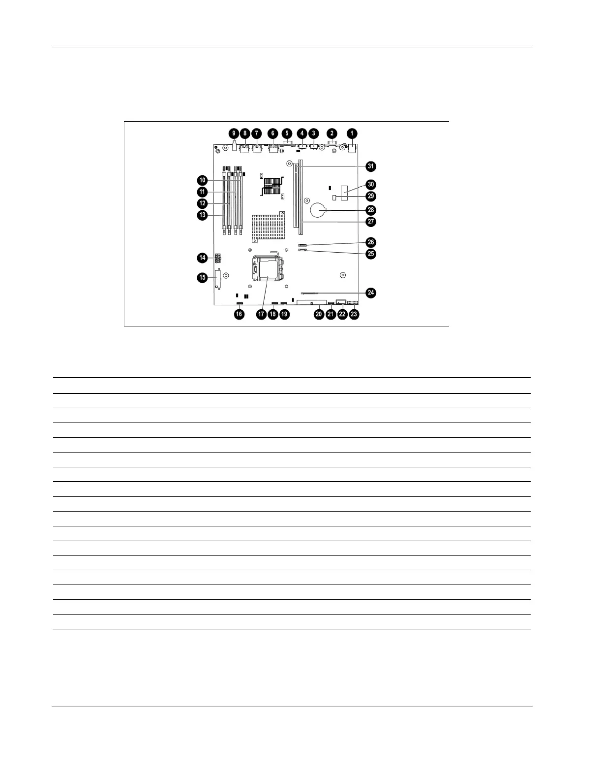
Figure 4-3 and Table 4-3 show system board connectors on the system board.
Figure 4-3: System board components
Table 4-3: System Board Components
Item Description Item Description
1 Rear USB connectors (2) 17 Processor socket
2 Video connector 18 Fan 2 connector
3 Mouse connector 19 Fan 3 connector
4 Keyboard connector 20 IDE connector
5 Serial connector 21 Fan 4 connector
6 iLO management port 22 Front USB cable connector
7 10/100/1000 NIC 1 23 Front panel LED board connector
8 10/100/1000 NIC 2 24 Diskette drive connector
9 Rear UID button/LED 25 SATA hard drive connector 2
10 DIMM slot 1 (Bank A) 26 SATA hard drive connector 1
11 DIMM slot 2 (Bank A) 27 PCI-X/PCI Express slot 2 riser connector*
12 DIMM slot 3 (Bank B) 28 System Battery
13 DIMM slot 4 (Bank B) 29 NMI button (SW3)
14 Power connector 30 System maintenance switch (SW1)
15 Power connector 31 PCI-X slot 1 riser connector*
16 Fan 1 connector
* Designations if the optional PCI riser board is installed.
 Loading...