5
Navigation button – Right
Base module only
6 Right magazine and mailslot access
7 Enter button Base module only
8 Right magazine release button
9 Navigation button – Down Base module only
10 USB port Base module only
11
Back/Return button
Base module only
12
OCP LEDs, left to right
• Ready, green
• Unit identification (UID), blue
• Clean, amber
• Attention, amber
• Error, amber
Base module only
13 Power button Base module only
14 Left magazine release button
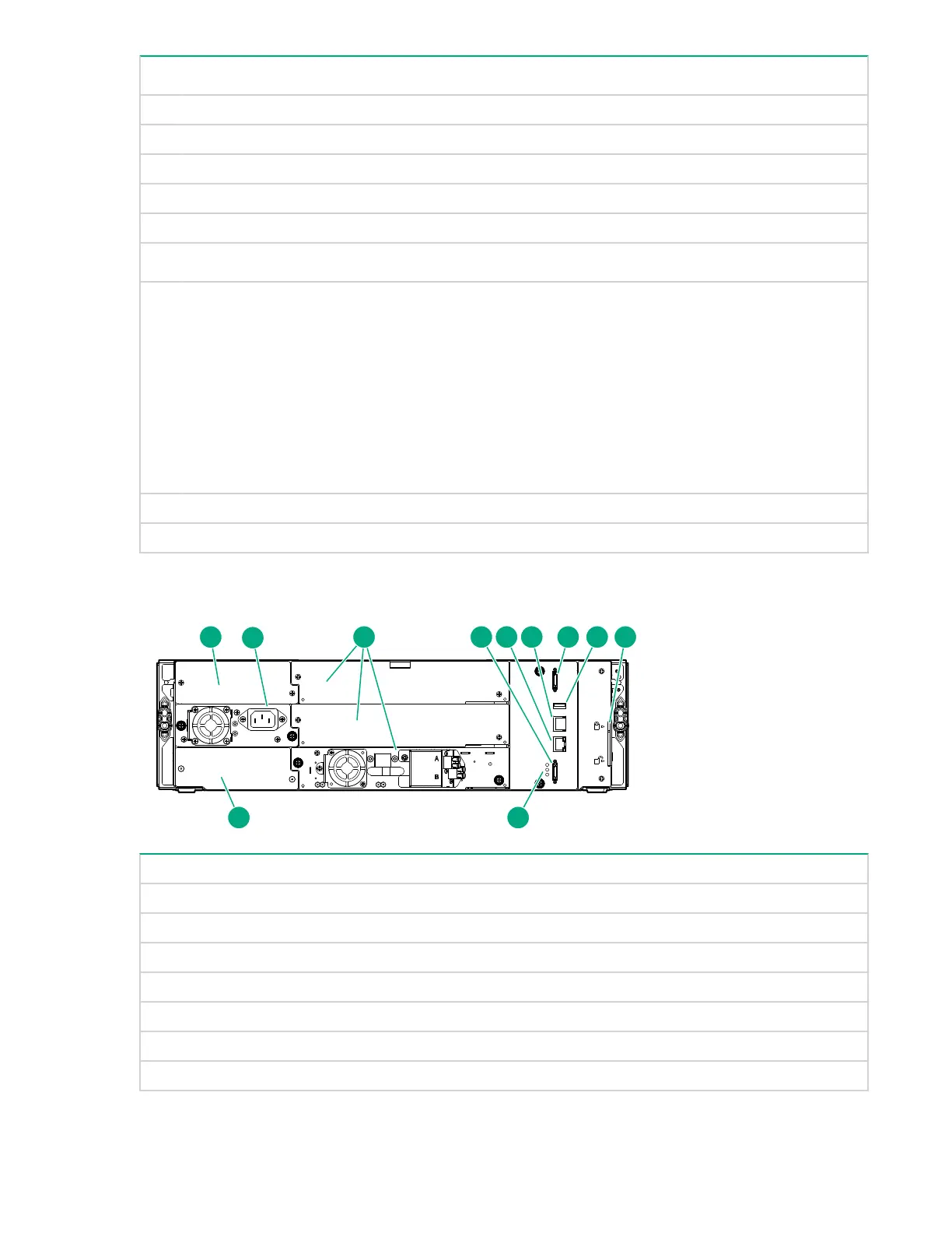
Rear panel
1 Power supply bay 1
2 Power supply bay 2
3 Half-height tape drive bays
4 Lower expansion module connection port
5 Ethernet MGMT - used for the RMI connection Base module only
6 Ethernet DIAG - used for the CVTL Data Verification connection Base module only
7 USB port Base module only
8 Upper expansion module connection port
Table Continued
10 Rear panel
 Loading...