105
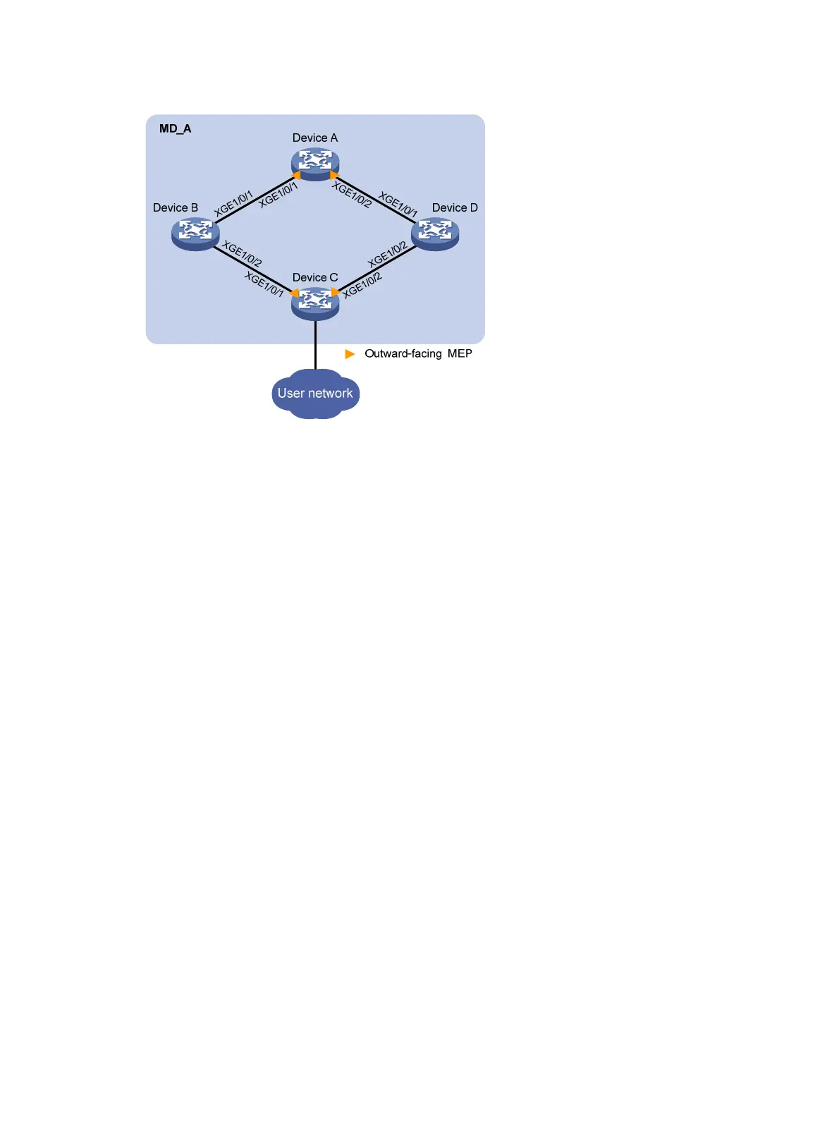
Figure 26 Network diagram
Configuration procedure
1. Configure Device A:
# Create VLAN 1 through VLAN 200.
<DeviceA> system-view
[DeviceA] vlan 1 to 200
# Configure Ten-GigabitEthernet 1/0/1 and Ten-GigabitEthernet 1/0/2 as trunk ports and assign
them to VLANs 1 through 200. Enable flush message receiving and configure VLAN 10 and
VLAN 110 as the receive control VLANs on Ten-GigabitEthernet 1/0/1 and Ten-GigabitEthernet
1/0/2.
[DeviceA] interface ten-gigabitethernet 1/0/1
[DeviceA-Ten-GigabitEthernet1/0/1] port link-type trunk
[DeviceA-Ten-GigabitEthernet1/0/1] port trunk permit vlan 1 to 200
[DeviceA-Ten-GigabitEthernet1/0/1] smart-link flush enable control-vlan 10 110
[DeviceA-Ten-GigabitEthernet1/0/1] quit
[DeviceA] interface ten-gigabitethernet 1/0/2
[DeviceA-Ten-GigabitEthernet1/0/2] port link-type trunk
[DeviceA-Ten-GigabitEthernet1/0/2] port trunk permit vlan 1 to 200
[DeviceA-Ten-GigabitEthernet1/0/2] smart-link flush enable control-vlan 10 110
[DeviceA-Ten-GigabitEthernet1/0/2] quit
# Enable CFD and create MD MD_A of level 5.
[DeviceA] cfd enable
[DeviceA] cfd md MD_A level 5
# Create service instance 1 in which the MA name is based on the VLAN ID in MD_A and
configure the MA to serve VLAN 10.
[DeviceA] cfd service-instance 1 ma-id vlan-based md MD_A vlan 10
# Create a MEP list in service instance 1, create outward-facing MEP 1002, and enable CCM
sending in service instance 1 on Ten-GigabitEthernet 1/0/1.
[DeviceA] cfd meplist 1001 1002 service-instance 1
[DeviceA] interface ten-gigabitethernet 1/0/1
[DeviceA-Ten-GigabitEthernet1/0/1] cfd mep 1002 service-instance 1 outbound

 Loading...


