138
Master IP : 10.1.1.2
The output shows that when Switch A fails, Switch B takes over to forward packets from Host A
to Host B.
# Recover the link between Host A and Switch A, and display detailed information about VRRP
group 1 on Switch A.
[SwitchA-Vlan-interface2] display vrrp verbose
IPv4 Virtual Router Information:
Running Mode : Standard
Total number of virtual routers : 1
Interface Vlan-interface2
VRID : 1 Adver Timer : 100
Admin Status : Up State : Master
Config Pri : 110 Running Pri : 110
Preempt Mode : Yes Delay Time : 500
Auth Type : None
Virtual IP : 10.1.1.111
Virtual MAC : 0000-5e00-0101
Master IP : 10.1.1.1
The output shows that after Switch A resumes normal operation, it becomes the master to
forward packets from Host A to Host B.
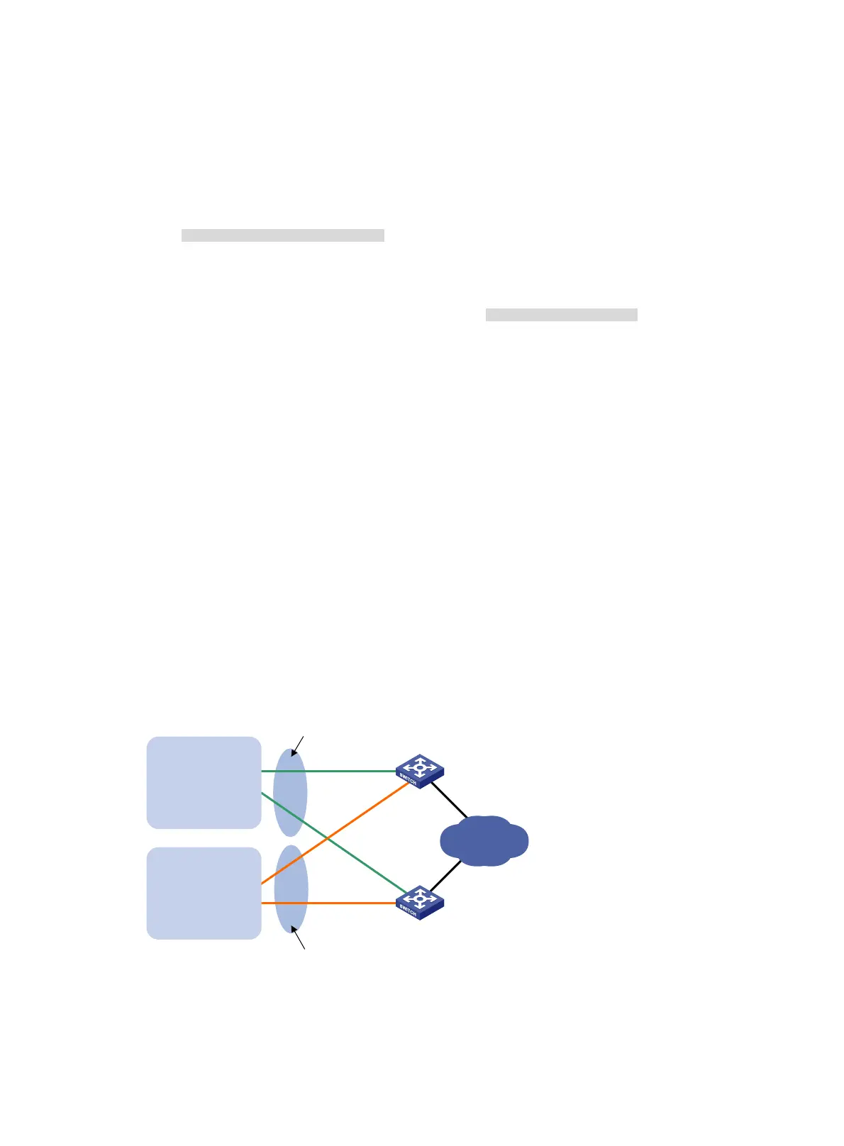
Multiple VRRP groups configuration example
Network requirements
Switch A and Switch B form two VRRP groups. VRRP group 1 uses the virtual IP address
10.1.1.100/25 to provide gateway service for hosts in VLAN 2, and VRRP group 2 uses the virtual IP
address 10.1.1.200/25 to provide gateway service for hosts in VLAN 3, as shown in Figure 38.
Assig
n a higher priority to Switch A than Switch B in VRRP group 1, but a lower priority in VRRP
group 2, to distribute the traffic from VLAN 2 and VLAN 3 between the two switches. When one of the
switches fails, the healthy switch provides gateway service for both VLANs.
Figure 38 Network diagram
Configuration procedure
1. Configure Switch A:
Switch A
Switch B
Virtual IP address 1:
10.1.1.100/25
Virtual IP address 2:
10.1.1.200/25
XGE1/0/5
Vlan-int2
10.1.1.1/25
XGE1/0/5
Vlan-int2
10.1.1.2/25
Internet
VLAN 2
Gateway:
10.1.1.100/25
VLAN 3
Gateway:
10.1.1.200/25
XGE1/0/6
Vlan-int3
10.1.1.130/25
XGE1/0/6
Vlan-int3
10.1.1.131/25

 Loading...