51
Figure 17 Schematic diagram for a single-ring load balancing network
Intersecting-ring load balancing
In an intersecting-ring network, you can also achieve load balancing by configuring multiple
domains.
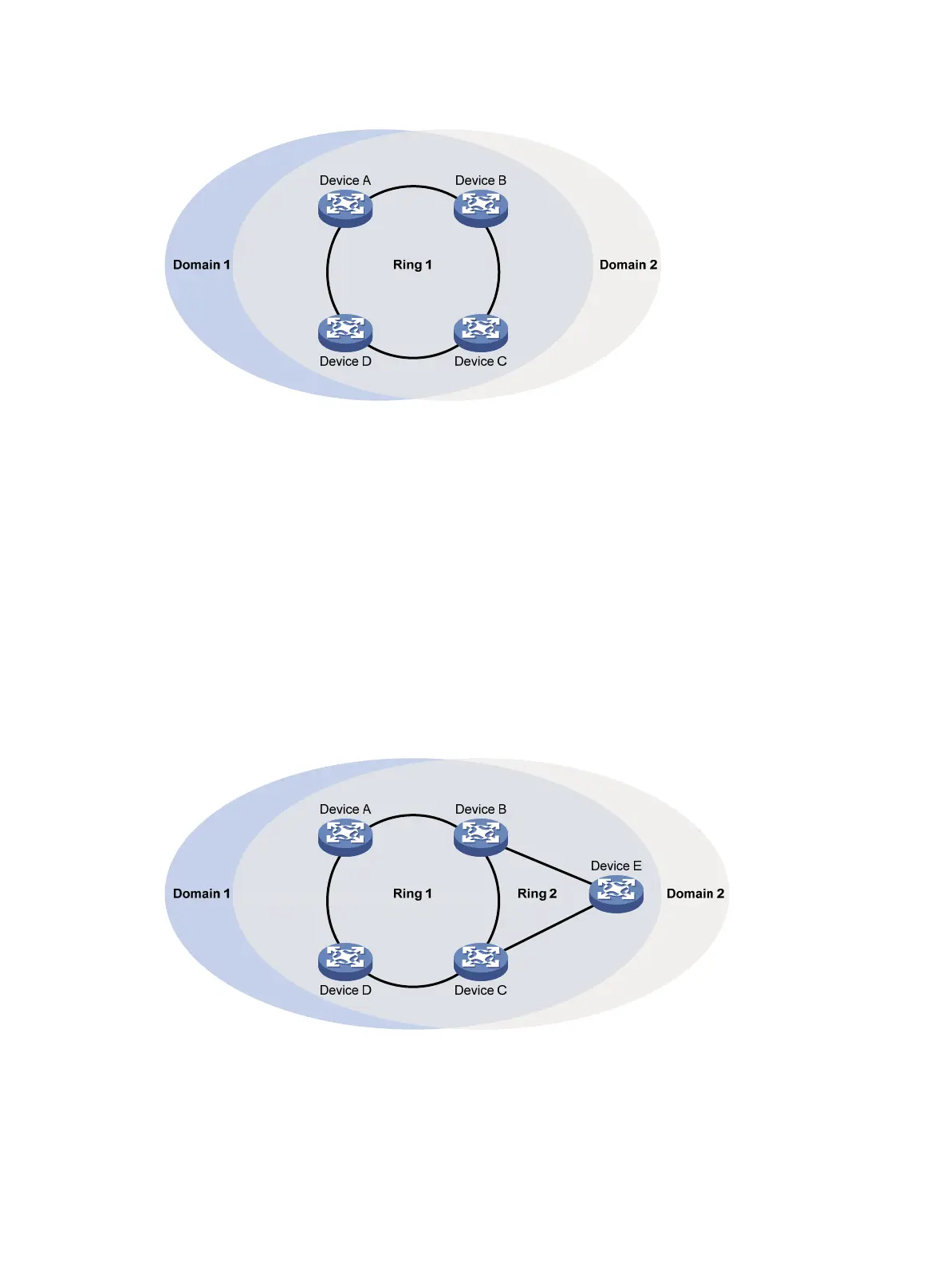
As shown in Figure 18:
• Ring 1 i
s the primary ring and Ring 2 is the subring in both Domain 1 and Domain 2.
• Domain 1 and Domain 2 are configured with different protected VLANs.
• Device A is configured as the master node of Ring 1 in Domain 1.
• Device D is configured as the master node of Ring 1 in Domain 2.
• Device E is configured as the master node of Ring 2 in both Domain 1 and Domain 2. However,
different ports on Device E are blocked in Domain 1 and Domain 2.
With the configurations, you can enable traffic from different VLANs to travel over different paths in
the subring and primary ring, achieving intersecting-ring load balancing.
Figure 18 Schematic diagram for an intersecting-ring load balancing network
Protocols and standards
RFC 3619, Extreme Networks' Ethernet Automatic Protection Switching (EAPS) Version 1.

 Loading...