136
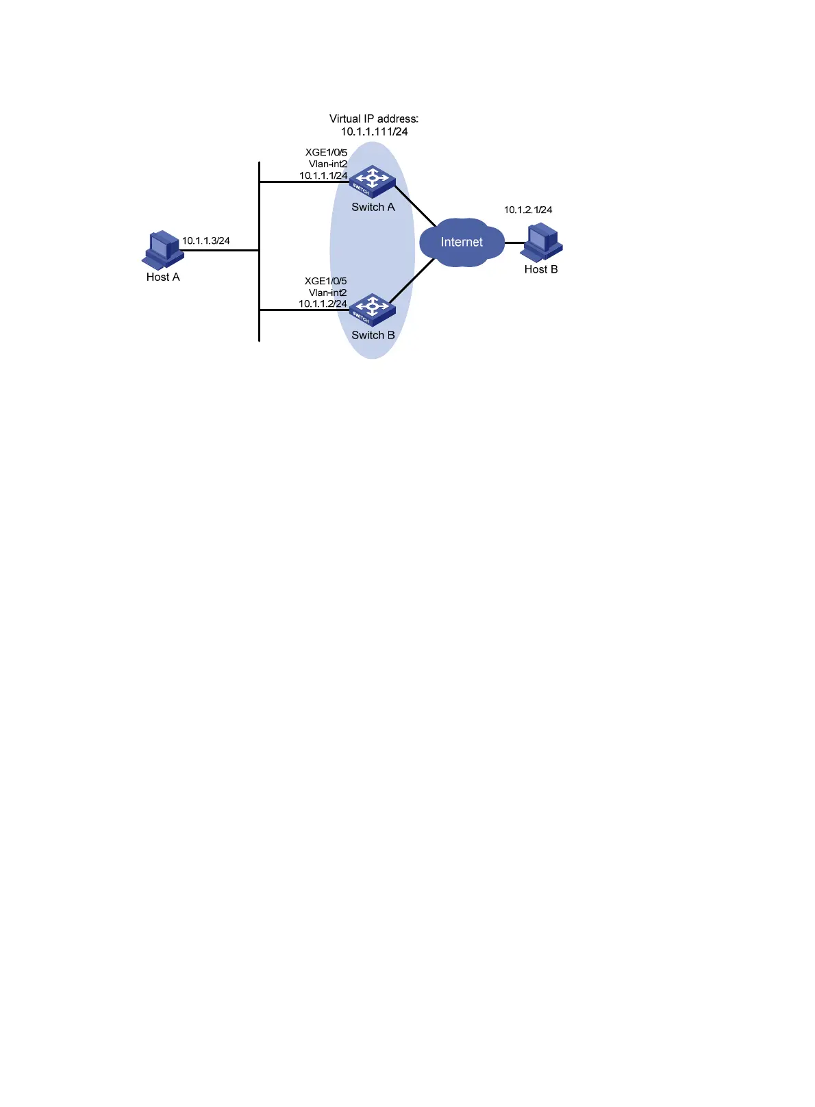
Figure 37 Network diagram
Configuration procedure
1. Configure Switch A:
# Configure VLAN 2.
<SwitchA> system-view
[SwitchA] vlan 2
[SwitchA-vlan2] port ten-gigabitethernet 1/0/5
[SwitchA-vlan2] quit
[SwitchA] interface vlan-interface 2
[SwitchA-Vlan-interface2] ip address 10.1.1.1 255.255.255.0
# Create VRRP group 1 on VLAN-interface 2, and set its virtual IP address to 10.1.1.111.
[SwitchA-Vlan-interface2] vrrp vrid 1 virtual-ip 10.1.1.111
# Assign Switch A a higher priority than Switch B in VRRP group 1, so Switch A can become the
master.
[SwitchA-Vlan-interface2] vrrp vrid 1 priority 110
# Configure Switch A to operate in preemptive mode, so it can become the master whenever it
operates correctly. Set the preemption delay to 500 centiseconds to avoid frequent status
switchover.
[SwitchA-Vlan-interface2] vrrp vrid 1 preempt-mode delay 500
2. Configure Switch B:
# Configure VLAN 2.
<SwitchB> system-view
[SwitchB] vlan 2
[SwitchB-Vlan2] port ten-gigabitethernet 1/0/5
[SwitchB-vlan2] quit
[SwitchB] interface vlan-interface 2
[SwitchB-Vlan-interface2] ip address 10.1.1.2 255.255.255.0
# Create VRRP group 1 on VLAN-interface 2, and set its virtual IP address to 10.1.1.111.
[SwitchB-Vlan-interface2] vrrp vrid 1 virtual-ip 10.1.1.111
# Configure the priority of Router B in VRRP group 1 as 100.
[SwitchB-Vlan-interface2] vrrp vrid 1 priority 100
# Configure Switch B to operate in preemptive mode, and set the preemption delay to 500
centiseconds.

 Loading...


