78
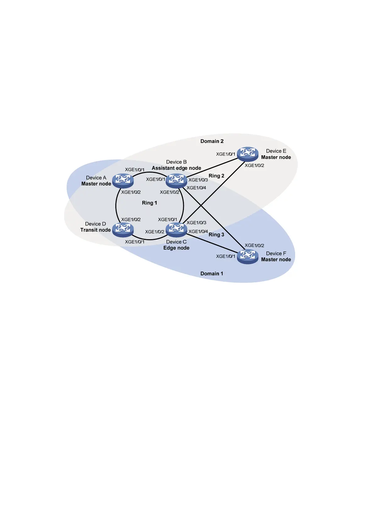
• Device A, Device B, Device C, Device D, and Device E form RRPP domain 2. VLAN 105 is the
primary control VLAN of the RRPP domain. Device A is the master node of the primary ring,
Ring 1. Device D is the transit node of Ring 1. Device E is the master node of the subring Ring
2. Device C is the edge node of the subring Ring 2. Device B is the assistant edge node of the
subring Ring 2.
• Specify VLAN 11 as the protected VLAN of domain 1, and VLAN 12 the protected VLAN of
domain 2. You can implement VLAN-based load balancing on Ring 1.
• Ring 2 and Ring 3 have the same edge node and assistant edge node, and the two subrings
have the same SRPTs. You can add Ring 2 and Ring 3 to an RRPP ring group to reduce
Edge-Hello traffic.
Figure 22 Network diagram
Configuration procedure
1. Configure Device A:
# Create VLANs 11 and 12.
<DeviceA> system-view
[DeviceA] vlan 11 to 12
# Map VLAN 11 to MSTI 1 and VLAN 12 to MSTI 2.
[DeviceA] stp region-configuration
[DeviceA-mst-region] instance 1 vlan 11
[DeviceA-mst-region] instance 2 vlan 12
# Activate the MST region configuration.
[DeviceA-mst-region] active region-configuration
[DeviceA-mst-region] quit
# Set the physical state change suppression interval to 0 seconds on Ten-GigabitEthernet
1/0/1.
[DeviceA] interface ten-gigabitethernet 1/0/1
[DeviceA-Ten-GigabitEthernet1/0/1] link-delay 0
# Disable the spanning tree feature on the port.
[DeviceA-Ten-GigabitEthernet1/0/1] undo stp enable
# Configure the port as a trunk port.

 Loading...


