38
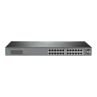
Figure 44 Rear panel
(1) Fiber management Ethernet port (2) Copper management Ethernet port
(3) Console port (4) Mini USB console port
(5) Fan tray 1 (6) Fan tray 2
(7) Fan tray 3 (8) Fan tray 4
(9) Fan tray 5 (10) Power supply 1
(11) Power supply 2 (12) USB port
(13) System status LED (SYS) (14) LINK/ACT LED for the copper management Ethernet port
(15) LINK/ACT LED for the fiber management Ethernet port
An HPE 5710-54HT switch comes with power supply slot PWR1 empty and power supply slot PWR2
installed with a filler module. In Figure 44, two PSR450-12A1 po
wer supplies are installed in the
power supply slots. For more information about installing and removing a power supply, see
"Installing and removing a power supply."
An HPE 5710-54HT switch comes with the five fan tray slots empty. You must install five fan trays of
the same model for the switch. In Figure 44, five
X721 front-to-back fan trays are installed in the fan
tray slots. For more information about installing and removing a fan tray, see "Installing and removing
a fan tray."
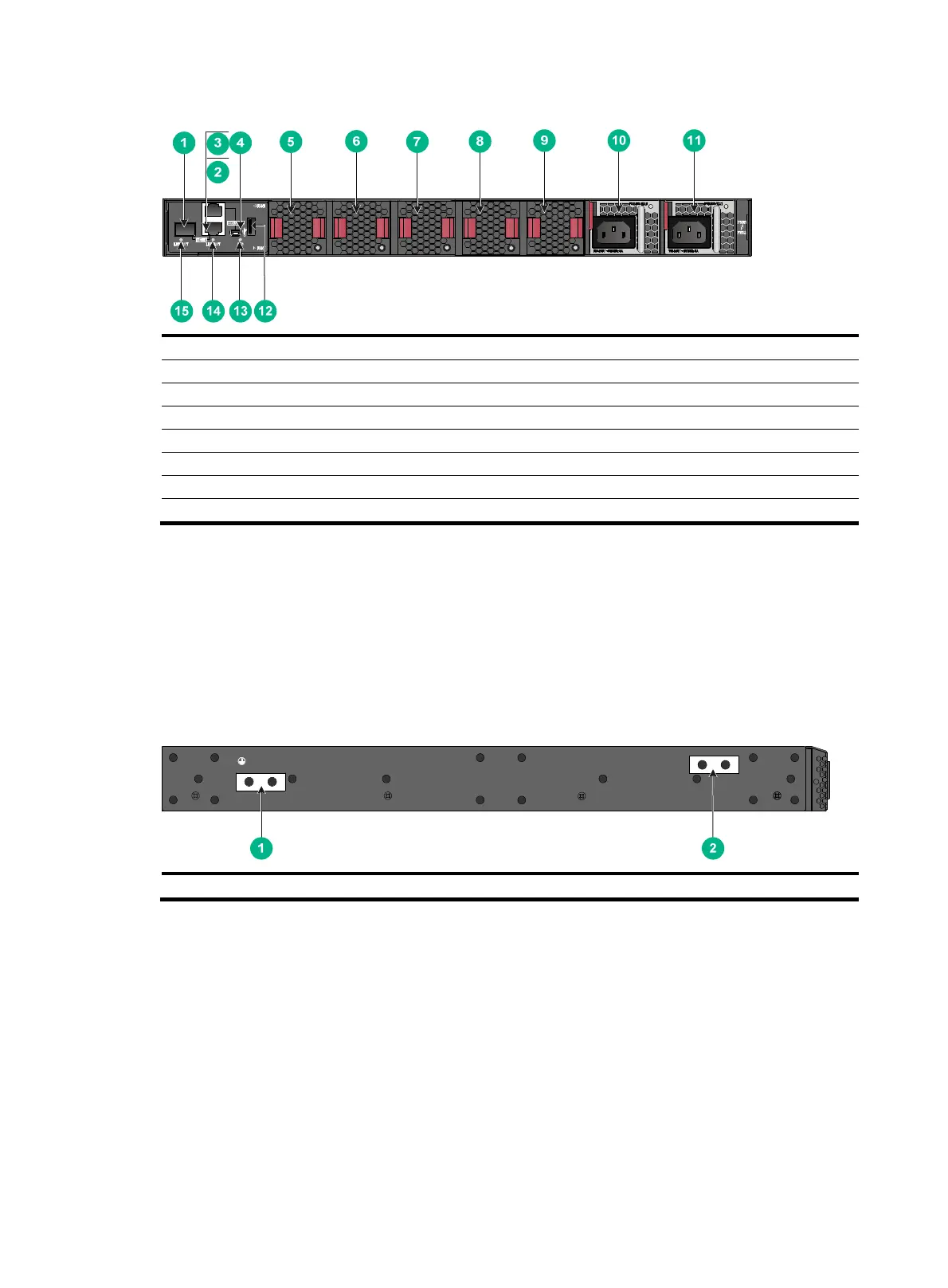
Figure 45
Left side panel
(1) Primary grounding point (2) Auxiliary grounding point

 Loading...