7
The HPE 1950 24G 2SFP+ 2XGT PoE+(370W) and HPE 1950 48G 2SFP+ 2XGT PoE+(370W)
switches provide one front mounting position (near the network ports), one mid-mounting position,
and one rear mounting position (near the power supplies).
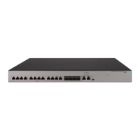
To attach the mounting brackets to the switch:
1. Determine the mounting position.
2. Align one mounting bracket with the screw holes at the mounting position. Use M4 screws
provided with the switch to attach the mounting bracket to the chassis.
3. Repeat step 2 to attach the other mo
unting bracket to the chassis.
Figure 4 Attaching a two-hole mounting bracket to the front mounting position on an HPE
1950 24G 2SFP+ 2XGT switch
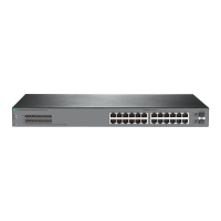
Figure 5 Attaching a two-hole mounting bracket to the rear mounting position on an HPE
1950 24G 2SFP+ 2XGT switch
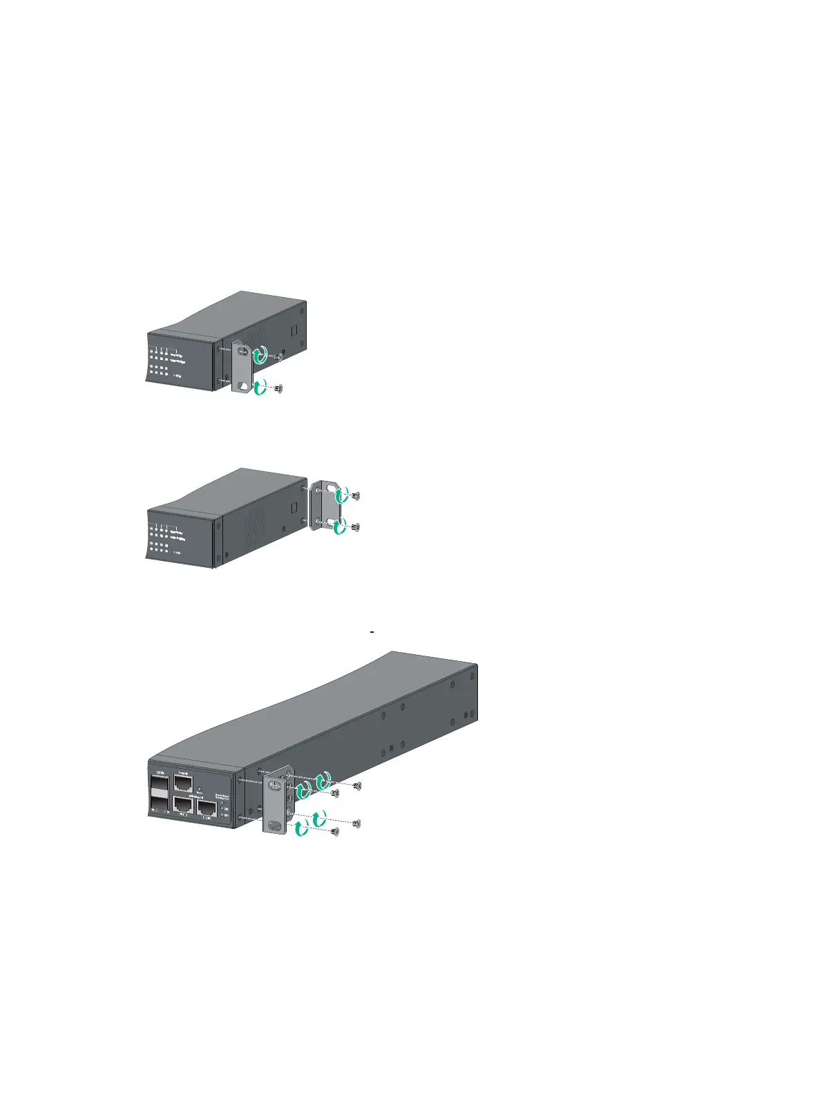
Figure 6 Attaching a four-hole mounting bracket to the front mounting position on an HPE
1950 24G 2SFP+ 2XGT PoE+(370W)
switch

 Loading...