7. Remove the chassis cover.
8. Remove the system board assembly.
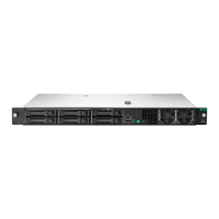
9. Remove the iLO enablement module blank.
Retain the blank for future use.
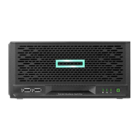
10.
Install the iLO enablement module (callout 1), and then install the screw on the rear panel (callout 2). Make sure that
the module is firmly seated in the slot.
11. Install the server board assembly.
12.
Install the chassis cover.
13. If removed, install the security padlock and/or the Kensington security lock.
For more information, see the lock documentation.
14. Connect all peripheral cables to the server.
15. Connect the power adapter to the server, and then secure the power adapter cord in the power cord clip.
Hardware options installation
55