Shenzhen Hpmont Technology Co., Ltd. Chapter 6 Function Introduction
HD3N Series User Manual V1.1 - 81 -
Ref. code Function Description Setting Range [Default]
38: High speed pulse output (DO2 only).
• Refer to F16.21.
Terminal output logic setting
Terminal input logic setting. Defines that each bit (binary) represents different physical sources.
• 0: Positive logic. Connected to corresponding common port,
this logic is enabled. Otherwise disabled.
• 1: Negative logic. Connected to corresponding common port,
this logic is disabled. Otherwise enabled.
Bit3 Bit2 Bit1 Bit0
- R LY 1 DO2 DO1
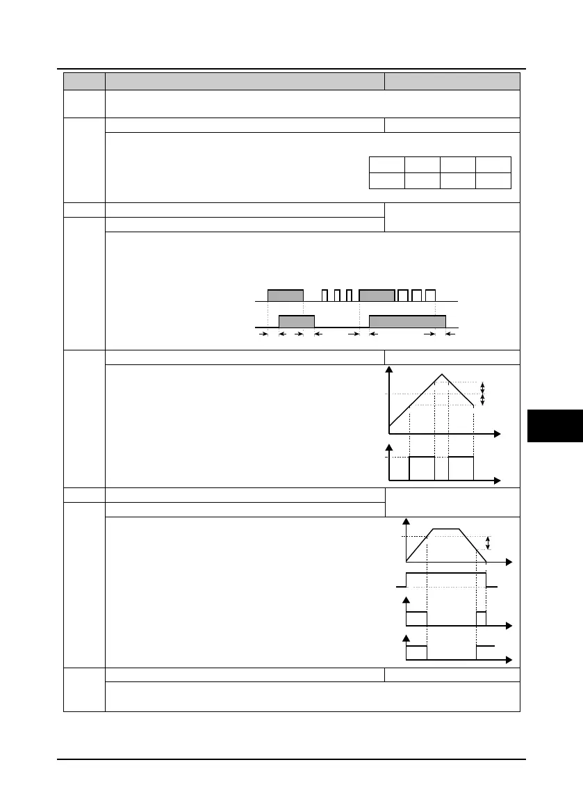
Delay time at ON side for timing
0.00 - 300.00 [0.00s]
F15.26 Delay time at OFF side for timing
F15.25, F15.26 set delay time (dead zone) at ON/OFF side for timming function, relating to input.
• Timing function output is ON when time of timing function input > F15.25.
• Timing function output is OFF when time of timing function input < F15.25.
Below is figure of timing function action:
F15.27 Speed within FAR ran ge 0.00 - 100.00 [2.50Hz]
The pulse signal will output if elevator speed is within
the FAR range. As shown in the right figure.
0.00 - upper limit frequency
[0.00Hz]
F15.28 and F15.29 defines the zero speed output
control function.
F15.30 FDT1 detection mode 0,1 [0]
0: Detect according to setting frequency.
1: Detect according to output frequency.
ON ON
ON ON
Timing functioninput
Timing functionoutput
F15.25 F15.25F15.26 F15.26
Output
Output
Time
Time
Preset frequency
DO
F15.27
F15.27
Running frequency
Zero-frequency
running output
F15.29
F15.28
Running status
Zero-frequency output
Time
Time
Time

 Loading...

